Method of mounting electronic component and electronic component mounting apparatus

a technology of electronic components and mounting apparatuses, which is applied in the direction of manufacturing tools, instruments, transportation and packaging, etc., can solve the problem of complicated work of inputting the coordinates of the measurement positions

Active Publication Date: 2008-10-30
YAMAHA MOTOR CO LTD
View PDF6 Cites 11 Cited by
  • Summary
  • Abstract
  • Description
  • Claims
  • Application Information

AI Technical Summary

Problems solved by technology

In some cases, due to a warp of a printed board, electronic micro-components may be brought back instead of mounted, crack, or scatter solders in the mounting operation.
However, a plurality of posit...

Method used


Image

  • Method of mounting electronic component and electronic component mounting apparatus
  • Method of mounting electronic component and electronic component mounting apparatus
  • Method of mounting electronic component and electronic component mounting apparatus

Examples


Embodiment Construction

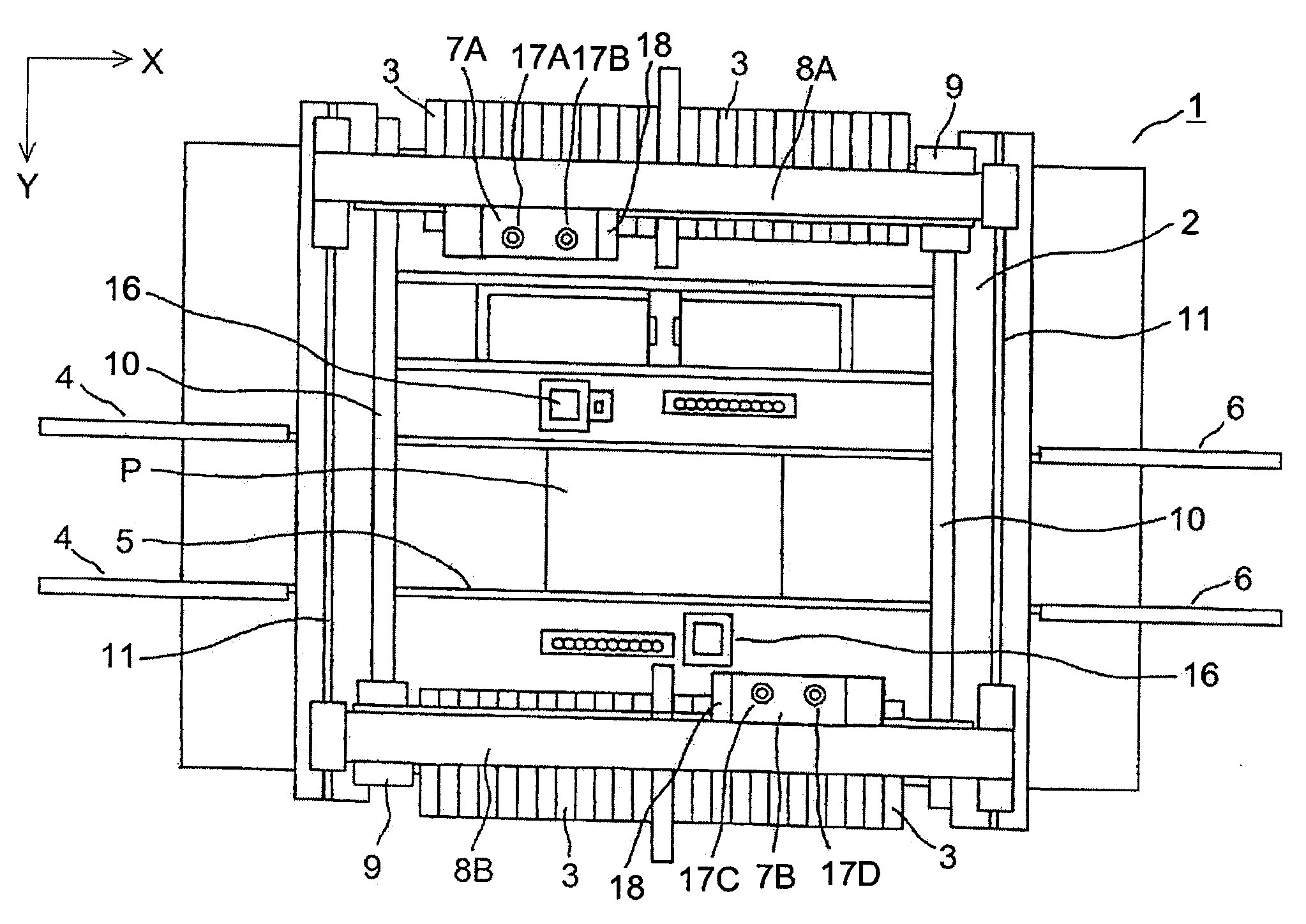
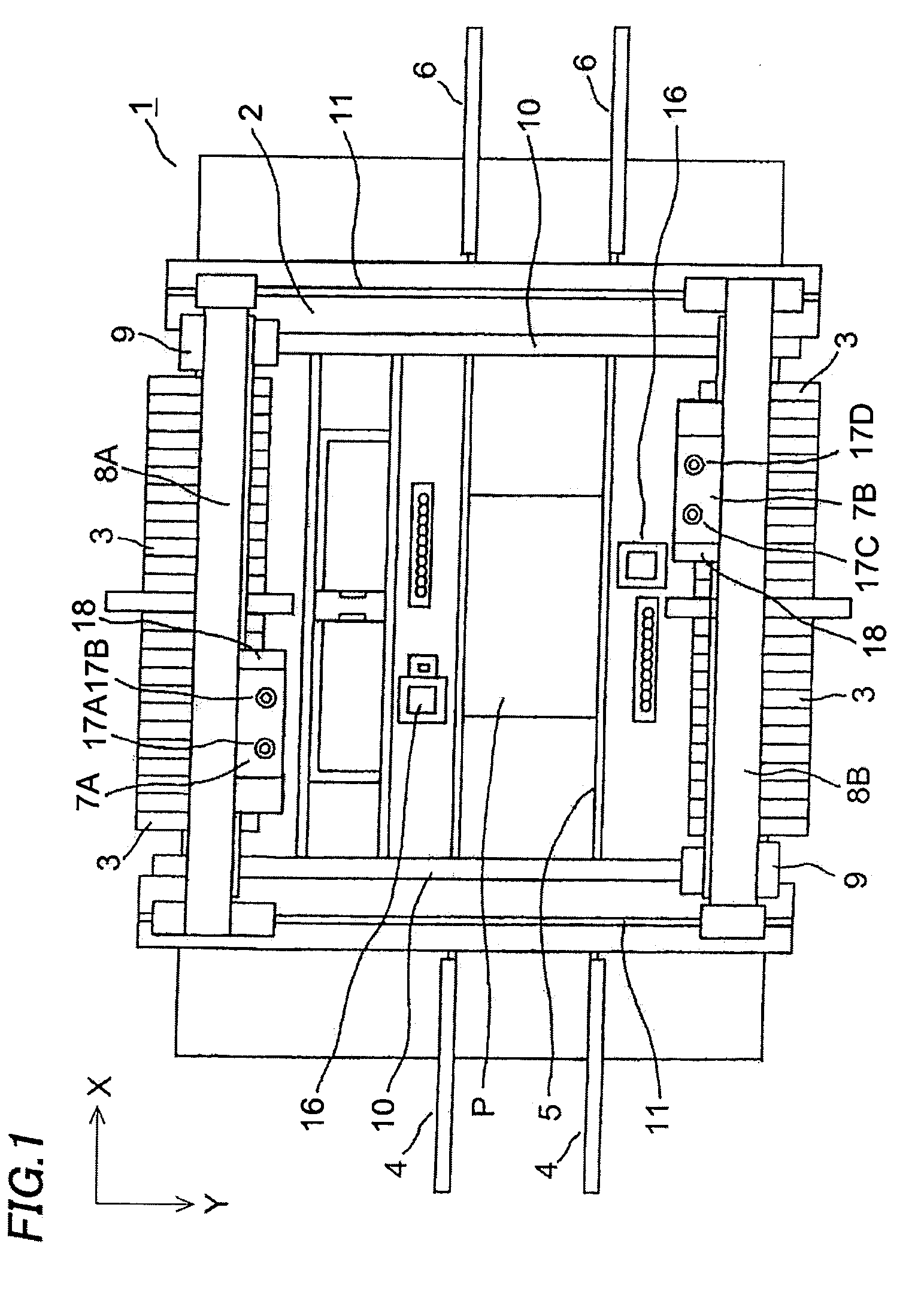
[0017]An embodiment of an electronic component mounting apparatus for mounting electronic components on a printed board will be described referring to figures. FIG. 1 is a plan view of an electronic component mounting apparatus 1, and a plurality of component feeding units 3 supplying various electronic components to these component pickup portions (component suction positions) one by one is arrayed on a base 2 of the apparatus 1. A supplying conveyer 4, a positioning portion 5 and a discharging conveyer 6 are provided between the opposite groups of component feeding units 3. The supplying conveyer 4 carries a printed board P received from an upstream device to the positioning portion 5, the printed board P is positioned by a positioning mechanism (not shown) on the positioning portion 5, electronic components are mounted on the printed board P, and the printed board P is carried to the discharging conveyer 6.

[0018]Numerals 8A and 8B indicate a pair of beams extending in the X direc...


PUM

PropertyMeasurementUnit
Heightaaaaaaaaaa

Abstract

The invention realizes setting of measurement positions suitable for a warping state of a printed board and an easy work of setting the measurement positions. A printed board as a measurement sample is positioned three-dimensionally in X, Y and vertical directions on a positioning portion, and then a backup base is lifted up to apply backup pins to the back surface of the board and support the board horizontally. Then, the warping state of the board is measured by a height level detection device, and based on the measurement result the CPU displays the board on a monitor three-dimensionally or by contour lines. Once an operator sets measurement positions on the screen, the CPU converts each of the set positions into coordinates on the board, writes the coordinates of the set positions in the top of mounting data, and stores the data in the RAM. Then, in a manufacturing operation with a board, the height level detection device measures the height levels of the board in the set measurement positions according to the mounting data where the coordinates of the set positions are added and stores the measurement values in the RAM. The measurement values are used when electronic components are mounted on the board.

Description

CROSS-REFERENCE OF THE INVENTION[0001]This application claims priority from Japanese Patent Application No. 2007-117762, the content of which is incorporated herein by reference in its entirety.BACKGROUND OF THE INVENTION[0002]1. Field of the Invention[0003]The invention relates to an electronic component mounting apparatus for picking up electronic components from a component feeding device by suction by suction nozzles and mounting the electronic components on a positioned printed board. In detail, the invention relates to a method of mounting an electronic component and an electronic component mounting apparatus in which electronic components are picked up from a component feeding device by suction by suction nozzles, a height level of a positioned printed board is measured by a height level detection device, and the electronic components are mounted on the printed board based on the measurement result of this height level detection device.[0004]2. Description of the Related Art[...

Claims


Application Information

Patent Timeline
IPC IPC(8): G01R31/28H05K13/04
CPCH05K13/0069H05K13/0452Y10T29/5313Y10T29/49131Y10T29/53191Y10T29/49004Y10T29/53052Y10T29/4913H05K13/082B23P19/00
Inventor ONISHI, SEIJI
Owner YAMAHA MOTOR CO LTD
Why Eureka
Try Eureka