Powered Rotor for Assisting Crop Pickup for a Baler

a rotor and baler technology, applied in baling, agriculture tools and machines, baling, etc., can solve the problems of increasing and decreasing the revolutions per minute of the control, corn stalks that cannot be easily pushed along, and corn stalks that cannot be easily pushed into the baler pickup, so as to increase the efficiency of baling crop materials

Active Publication Date: 2008-10-30
WOODFORD ERIC T
View PDF33 Cites 31 Cited by
  • Summary
  • Abstract
  • Description
  • Claims
  • Application Information

AI Technical Summary

Benefits of technology

The technical effect of this patent is to improve the process of baling crops with a baler by making it more efficient.

Problems solved by technology

The technical problem addressed in this patent text relates to improving the performance of balers used to bale various types of crop materials, particularly corn stalls. Existing balers struggle to effectively move the crop material from the ground to the baling chamber due to issues related to the pickup portion of the machine. These challenges include slow speeds caused by incomplete crop input, unstable crop output resulting in poor bale formation, excessive pressure on the machinery leading to repair costs, and potential danger to operational safety. To address these concerns, the patent proposes design improvements aimed at achieving a more uniform and effective flow of crop material throughout the pickup portion of the baler.

Method used


Image

  • Powered Rotor for Assisting Crop Pickup for a Baler
  • Powered Rotor for Assisting Crop Pickup for a Baler
  • Powered Rotor for Assisting Crop Pickup for a Baler

Examples


Embodiment Construction

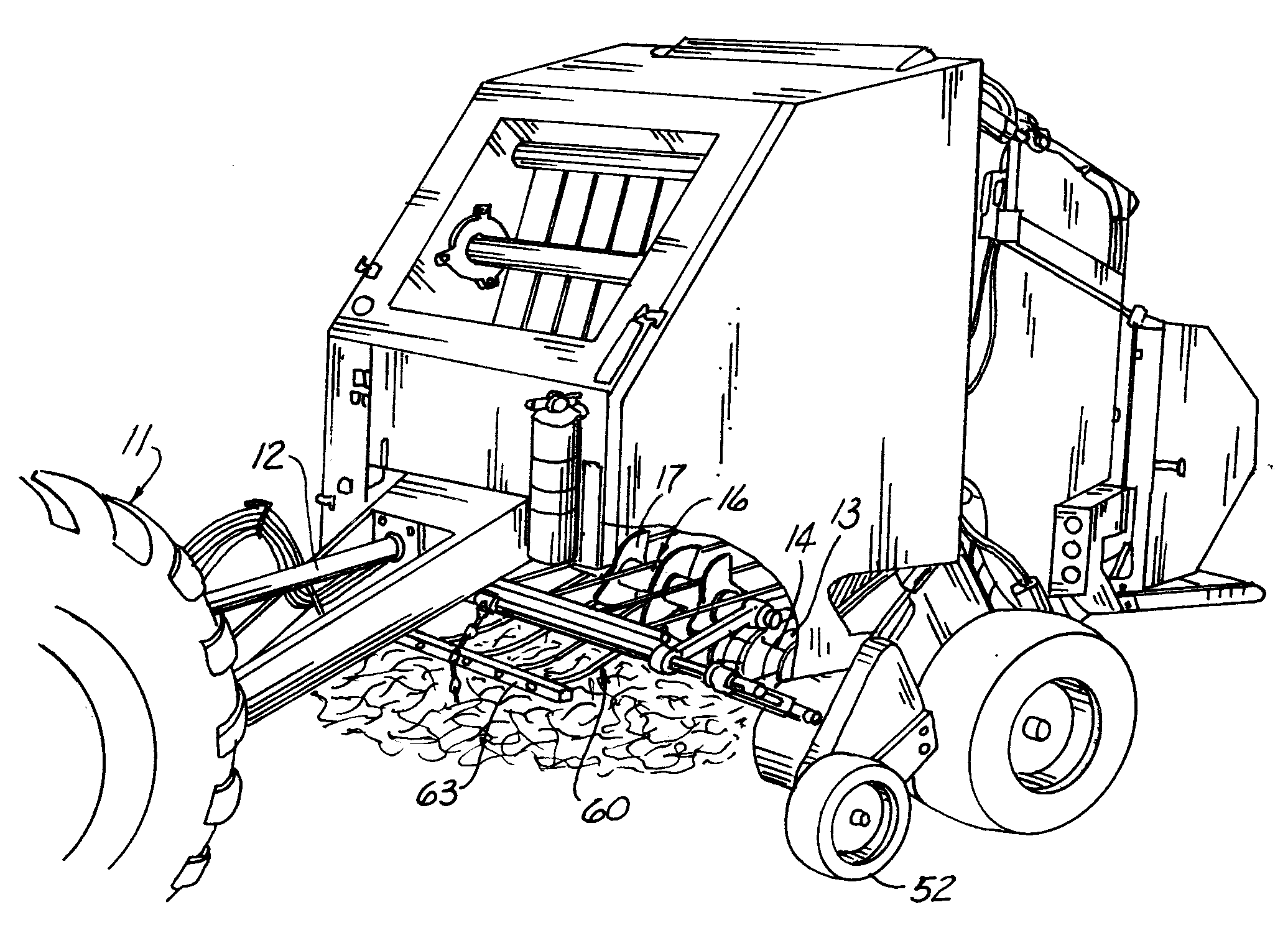
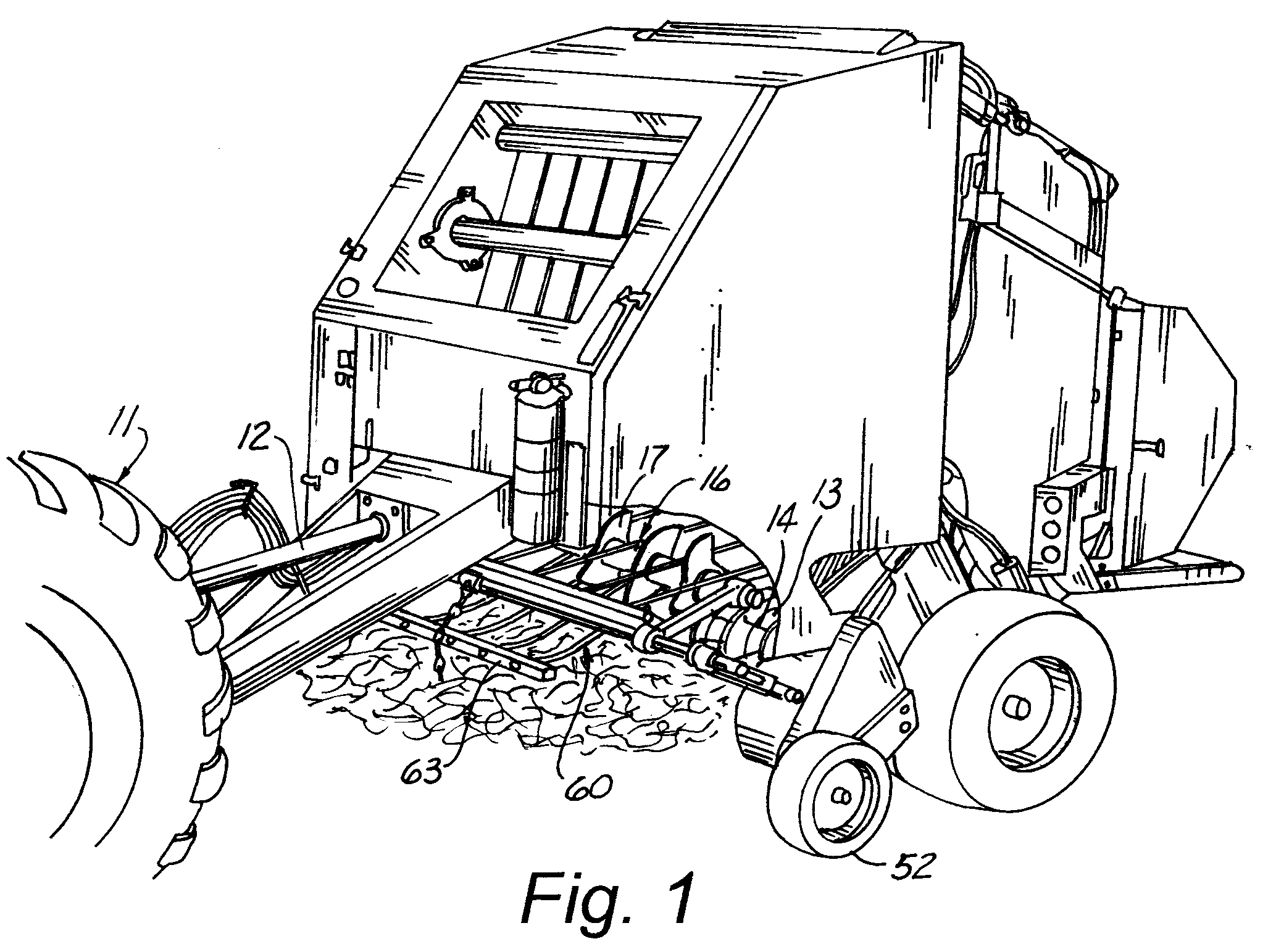
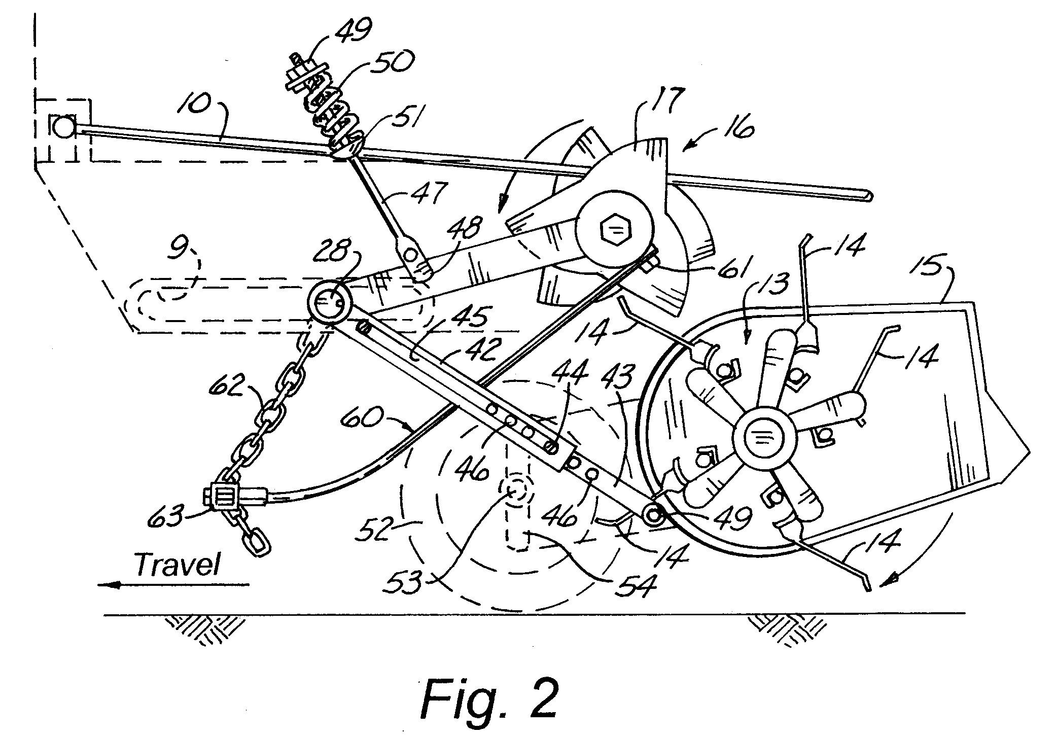
[0031]Referring now to the drawings wherein like reference numerals designate identical or similar parts throughout the several views, a preferred embodiment 1 of the present invention is illustrated in FIG. 1. The baler can, for example, be like the basic baler of U.S. Pat. No. 4,910,940 to Meyer, which is incorporated herein by reference in its entirety, though a more modern baler with more modern features can be used instead, for example the baler shown in U.S. Pat. No. 6,948,300 to Bandstra et. al, which is also incorporated herein by reference in its entirety. Of course it is to be understood that this invention can be used on any other type of baler, for example those that produce bales of a non-cylindrical shape, because the pickup sections of all prior art balers have crop material flow problems from time to time in the pickup sections thereof that could be solved by this invention.

[0032]The baler shown in FIG. 1 is towed by a tractor 11. The tractor 11 powers the baler thro...


PUM


Abstract

A method and apparatus for baling crop materials using a baler with a pickup thereon for picking up crop materials from the ground and moving such crop materials towards a baling chamber. The pickup has a pickup frame operatively attached to the baler, the frame having a plurality of laterally spaced apart tines of a type which is typical for balers. A powered rotor is rotationally attached to the baler a predetermined distance above and forwardly of the pickup frame, the rotor being powered to rotate in at least one direction. A plurality of blade assemblies are disposed on the rotor having blades extending radially outwardly from the axis of the rotor wherein at least at times one or more of the blade assemblies are disposed between one or more of the tines whereby adjacent blades which are below the axis of rotation of the rotor can be selectively moved towards the baling chamber to assist the pickup tines to move the crop materials into the baling chamber when the rotor is powered in operative baling direction, whereby crop material will pass evenly through the pickup, minimizing the possibility of plugging of the pickup.

Description


Claims


Application Information

Patent Timeline
Owner WOODFORD ERIC T
Why Eureka
Try Eureka