Sleep apnea CPAP headgear

Inactive Publication Date: 2008-10-30
FISHMAN GRAHAM A
View PDF12 Cites 91 Cited by
  • Summary
  • Abstract
  • Description
  • Claims
  • Application Information

AI Technical Summary

Benefits of technology

[0004]It is an object of the present teachings to provide a system which alleviates the claustrophobia effects which could be associated with existing two horizontal band sleep apnea headgear. To this end, the teachings herein introduce a derivation of a traditional headgear available for a CPAP sleep apnea mask. In one embo

Problems solved by technology

Although there are many causes for the low equipment usage rate, often user's stop using the equipment because of the discomfort caused by the syst

Method used


Image

  • Sleep apnea CPAP headgear
  • Sleep apnea CPAP headgear
  • Sleep apnea CPAP headgear

Examples


Example

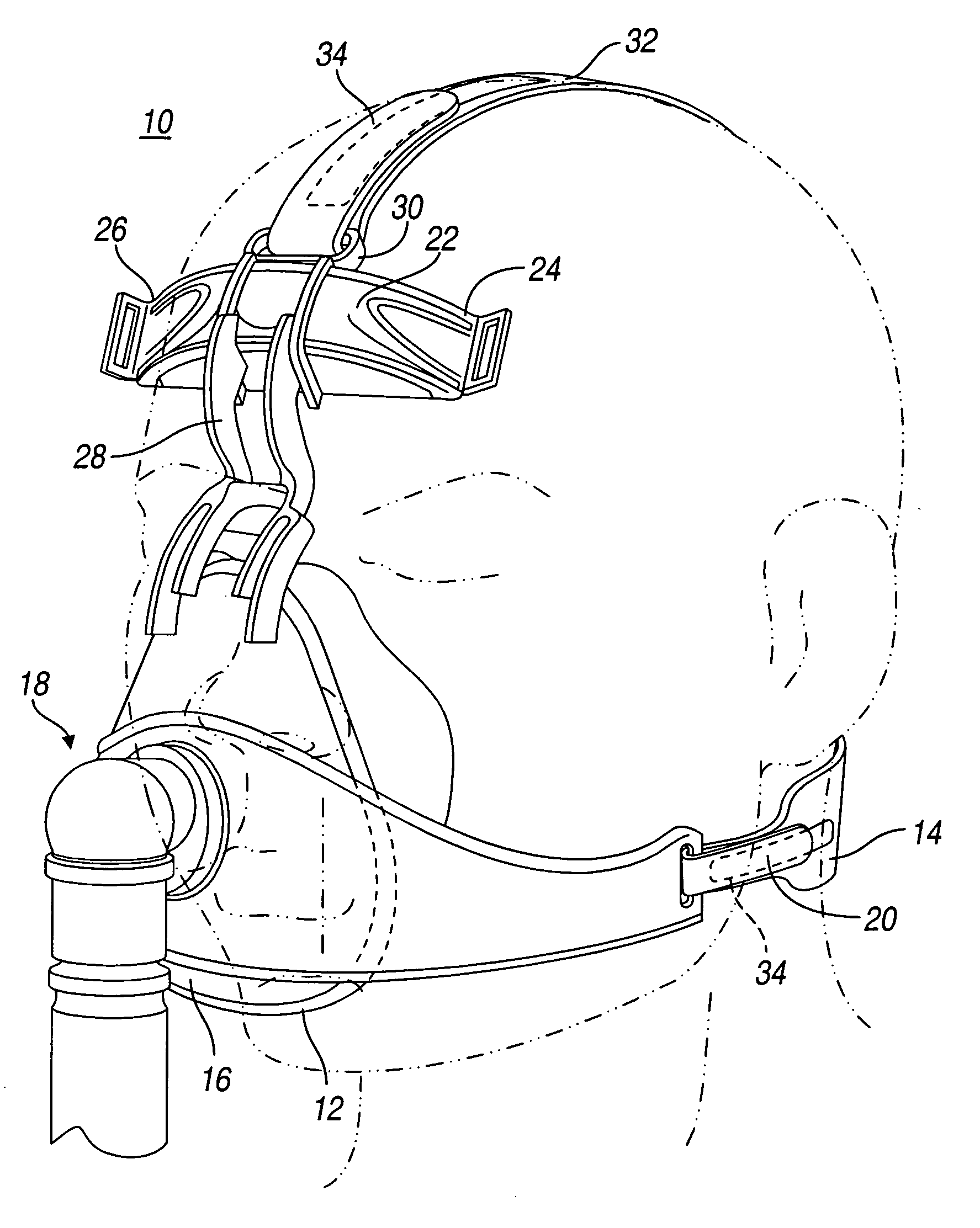
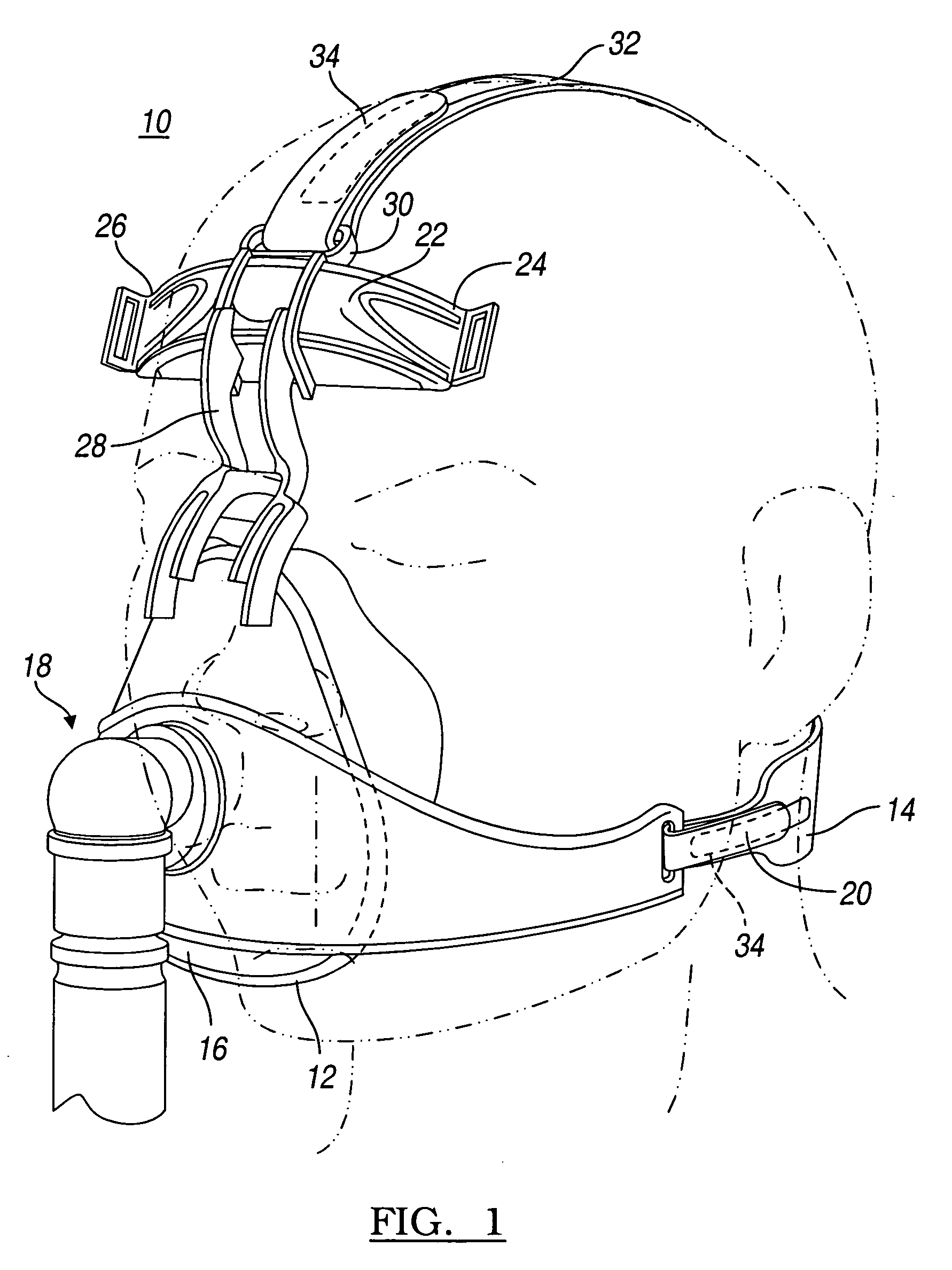
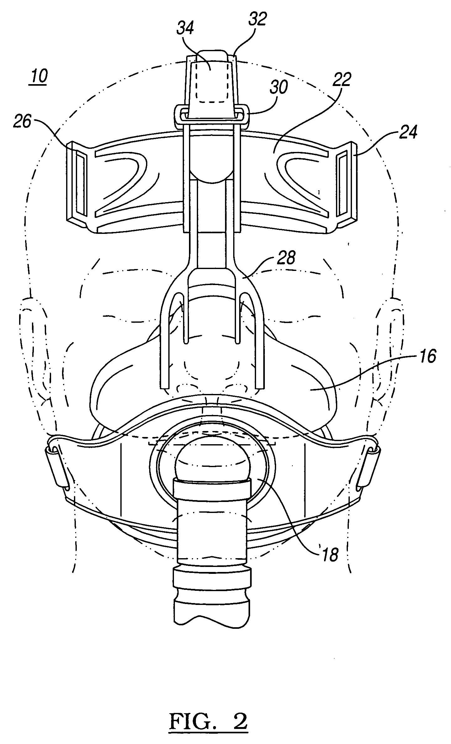
[0027]The following description of the preferred embodiments concerning an apparatus and method for retaining a sleep apnea mask on a patient is merely exemplary in nature and is in no way intended to limit the teachings, its application, or uses.

[0028]FIG. 1 shows a frontal view of the system 10 adapted to a sleep apnea mask 16. In this regard, the system 10 is configured to position a Respironics™ sleep apnea mask on the face of a patient. The prescription for the typical CPAP machine (not shown) coupled to the mask 16 may typically provide from zero (0) to twenty (20) CFM's (cubic feet per minute) positive pressure. The system 10 according to the present teaching is configured to maintain a minimum counterforce against the patient's face to ensure the CPAP pressure does not overtake and break the air-seal 12 application of the mask to the user's face. A horizontal band 14 is fixed on one side to the mask 16 which is positioned over the swivel airway intake spout 18. It is adjuste...


PUM


Abstract

A sleep apnea CPAP mask headgear system is provided which utilizes a vertical adjustable band along with a single lower horizontal adjustable band. The single horizontal strap is coupled to the sleep apnea CPAP mask using quick coupling fasteners. Spring biasing is applied to bias the mask to a user's face.

Description

CROSS-REFERENCE TO RELATED APPLICATIONS[0001]This application claims the benefit of U.S. Provisional Application No. 60 / 897,295, filed on Apr. 30, 2007; and U.S. Provisional Application No. 60 / 899,357, filed on Apr. 27, 2007; and U.S. Provisional Application No. 60 / 897,294, filed on Apr. 27, 2007. The disclosures of the above applications are incorporated herein by reference.FIELD[0002]The present disclosure relates to headgear for sleep apnea and more particularly to a headgear system for a CPAP mask for sleep apnea which increases the likelihood of CPAP system use.DISCUSSION OF THE RELATED ART[0003]Many people diagnosed with sleep apnea refrain from using the CPAP (Continuous Positive Airway Pressure) equipment on a regular basis. Reasons include the noise from the CPAP machine or the contact of the mask and associated headgear itself upon the nasal area. Although there are many causes for the low equipment usage rate, often user's stop using the equipment because of the discomfor...

Claims


Application Information

Patent Timeline
IPC IPC(8): A62B18/08
CPCA61M16/06A61M16/0683A61M16/0825A61M16/0638
Inventor FISHMAN, GRAHAM A.
Owner FISHMAN GRAHAM A
Why Eureka
Try Eureka