Sterilization apparatus

a technology of sterilization apparatus and sterilization chamber, which is applied in the field of sterilization devices, can solve the problems of substantially all biological contaminants that may be present on the data device, and achieve the effect of effectively removing substantially all contaminants and efficient configuration

Active Publication Date: 2008-10-30
HAND HELD PRODS
View PDF16 Cites 150 Cited by
  • Summary
  • Abstract
  • Description
  • Claims
  • Application Information

AI Technical Summary

Benefits of technology

[0013]The system of the present invention can be efficiently configured and designed to provide sterilization of the surfaces of a device by effectively removing substantially all contaminants including pathogenic substances. An apparatus for sterilizing surfaces of target devices from contamination by microorganisms comprises one or more walls which define an interior for containing UV radiation such that the interior can be proportionally sized to enclose a target device; a source of radiation comprising a plurality of LEDs such that the LEDs positioned can be positioned in combination with one or more walls; a power supply providing energy to the LEDs such that the LEDs emit UV radiation into the interior; and a holder or support enclosed by the one or more walls so that the plurality of UVLEDs in combination with the support expose substantially all surface areas of the target device to UV radiation. An opening or aperture in at least one wall may be present or an entire wall may be capable of opening to allow placement of the target device within the chamber.

Problems solved by technology

The method comprises enclosing a data device in a sterilization chamber comprising a distribution of UVLEDs where the UV radiation can be sealed within the interior confines of the chamber

Method used


Image

  • Sterilization apparatus
  • Sterilization apparatus
  • Sterilization apparatus

Examples


Embodiment Construction

[0023]In the following detailed description, for purposes of explanation and not limitation, exemplary embodiments disclosing specific details are set forth in order to provide a thorough understanding of the present invention. It will be apparent, however, to one having ordinary skill in the art that the present invention may be practiced in other embodiments that depart from the specific details disclosed herein. In other instances, detailed description of well-known devices and methods may be omitted so as not to obscure the description of the present invention.

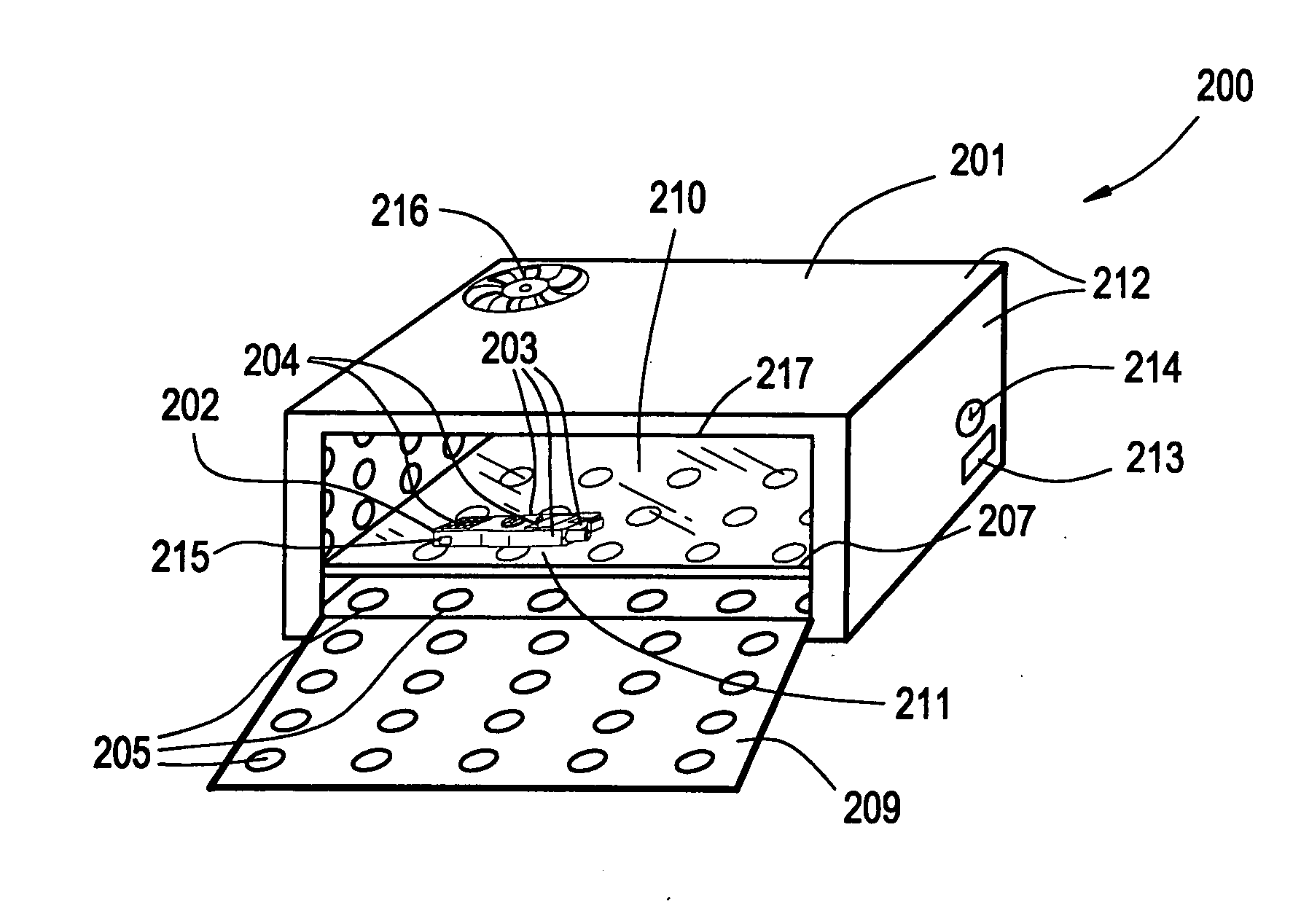
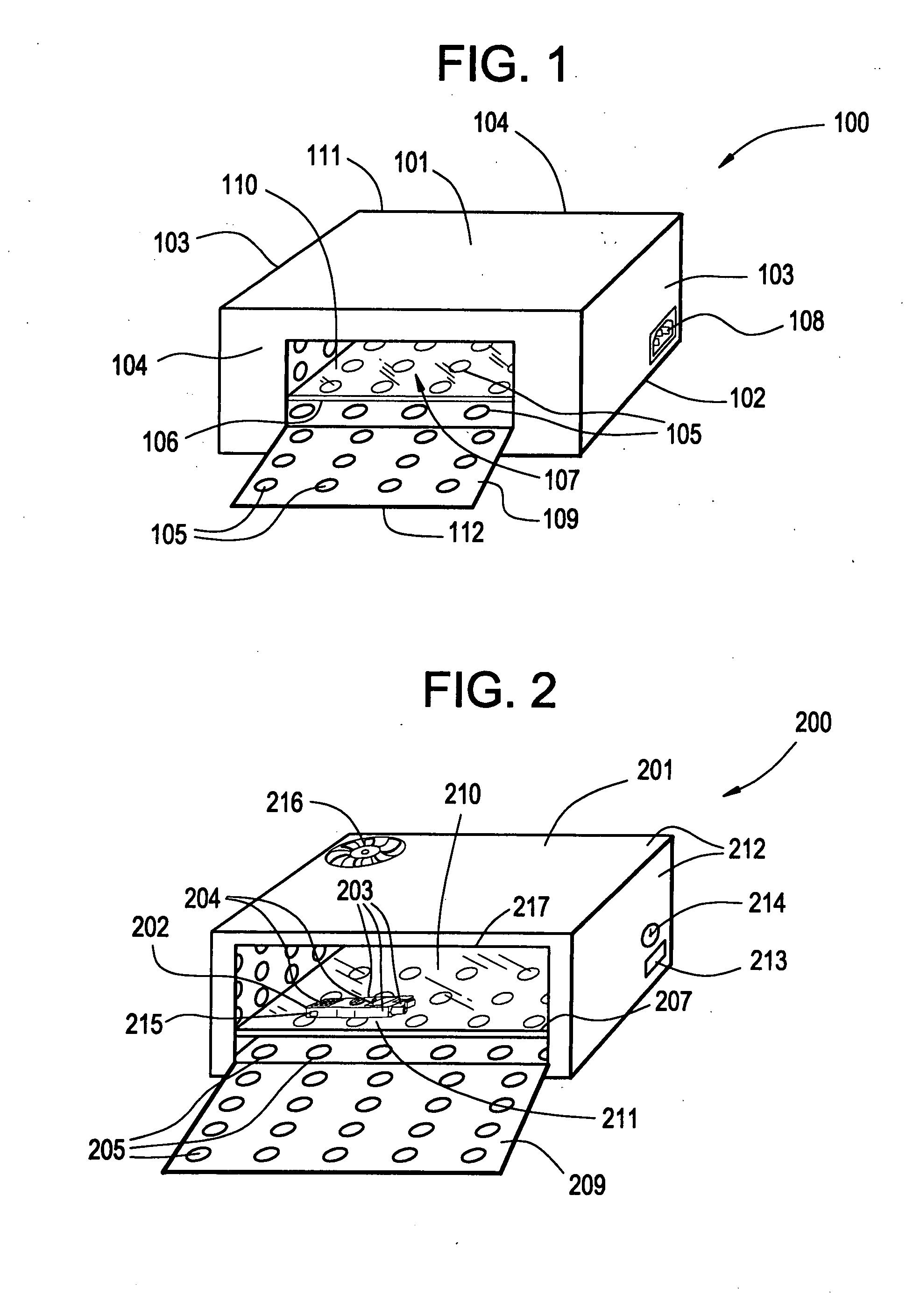
[0024]An external view of one embodiment of an apparatus is illustrated in FIG. 1. As illustrated, the apparatus 100 can take the form of a sterilization chamber 100. The sterilization chamber 100 comprises a top wall 101, a bottom wall 102, end walls 103 and side walls 104 which define the interior 110 of the chamber. Disposed within the chamber 100 are individual ultraviolet light emitting diodes (UVLEDs) 105 for irradia...


PUM


Abstract

Embodiments of a sterilization apparatus and methods of using a sterilization system are disclosed in the present application. The sterilization apparatus can take the form of a sterilization chamber comprising a top wall, a bottom wall, end walls and side walls which define the interior of the chamber. Throughout the interior of the chamber, multiple ultraviolet light emitting diodes (UVLEDs) irradiate energy at wavelengths for destroying pathogenic substances and achieving an efficient level of sterilization. A UV transparent plate located within the interior of the chamber can support one or more target devices, and can be proportionally sized to accommodate placement of a target device for the simultaneous and uniform distribution of UV sterilizing energy to the surfaces of a target. The sterilization chamber can provide the necessary decontamination and sterilization measures to effectively eliminate any residual biological contaminants on the exposed or hard-to-reach crevices or features of a medical device. Furthermore, one or more interior surfaces of the chamber may comprise a UV reflective material for distributing UV radiation upon substantially all surfaces of a target.

Description

FIELD OF THE INVENTION[0001]The present invention relates generally to sterilization devices. More particularly this invention relates to an apparatus for decontamination of instrumentation such as portable data terminals as used in the medical setting or clean-room environment.BACKGROUND OF THE INVENTION[0002]At the present time, existing technology utilizes equipment and instrumentation in the hospital setting and industrial clean-room environment requiring sterilization. Current cleaning methods, however, are not acceptable for decontaminating the various devices that have been implemented in these settings. In particular, data collection devices have become important in tracking vital signs of a patient and their location within the hospital. One such device includes the portable data terminal (PDT) used to communicate real-time information between patient and medical professional. For example, as medical professionals frequently monitor a number of patients in telemetry or tria...

Claims


Application Information

Patent Timeline
IPC IPC(8): A61L2/10
CPCA61L2/10
Inventor HAVENS, WILLIAM H.HENNICK, ROBERT J.
Owner HAND HELD PRODS
Why Eureka
Try Eureka