Rotary Electric Machine, Power Distribution Unit Therefor and Method for Assembling Rotary Electric Machine

Active Publication Date: 2008-10-30
HITACHI ASTEMO LTD
View PDF7 Cites 34 Cited by
  • Summary
  • Abstract
  • Description
  • Claims
  • Application Information

AI Technical Summary

Benefits of technology

[0015]An object of the present invention is to provide a power distribution unit that allows insulation distances between adjacent connecting rings of different phases to be secured, that is easy to be welded, and that can be reduced in size in the axial direction, at a low cost with productivity without increasing the number of parts.

Problems solved by technology

As a result, it is difficult to secure a distance necessary for achieving sufficient insulation from adjacent connecting rings of other phases.
Since the surface of the connecting ring around the through hole is planar, it is somewhat difficult to insert a coil terminal into the through hole.
Also, when welding of the coil terminal to the connecting ring is attempted, it is difficult to achieve an acceptable heat balance between the coil terminal to be welded and the connection ring since the volume of the molten part around the through hole is much larger than the volume of the coil terminal.
This makes it difficult to perform welding.
This inevitably results in broadening of a space on an edge of the stator in the axial direction to increase the size of the rotary electric machine in the axial direction.
Accordingly, many parts are necessary, which leads to an increase in the cost of parts and hence production cost.

Method used


Image

  • Rotary Electric Machine, Power Distribution Unit Therefor and Method for Assembling Rotary Electric Machine
  • Rotary Electric Machine, Power Distribution Unit Therefor and Method for Assembling Rotary Electric Machine
  • Rotary Electric Machine, Power Distribution Unit Therefor and Method for Assembling Rotary Electric Machine

Examples


Embodiment Construction

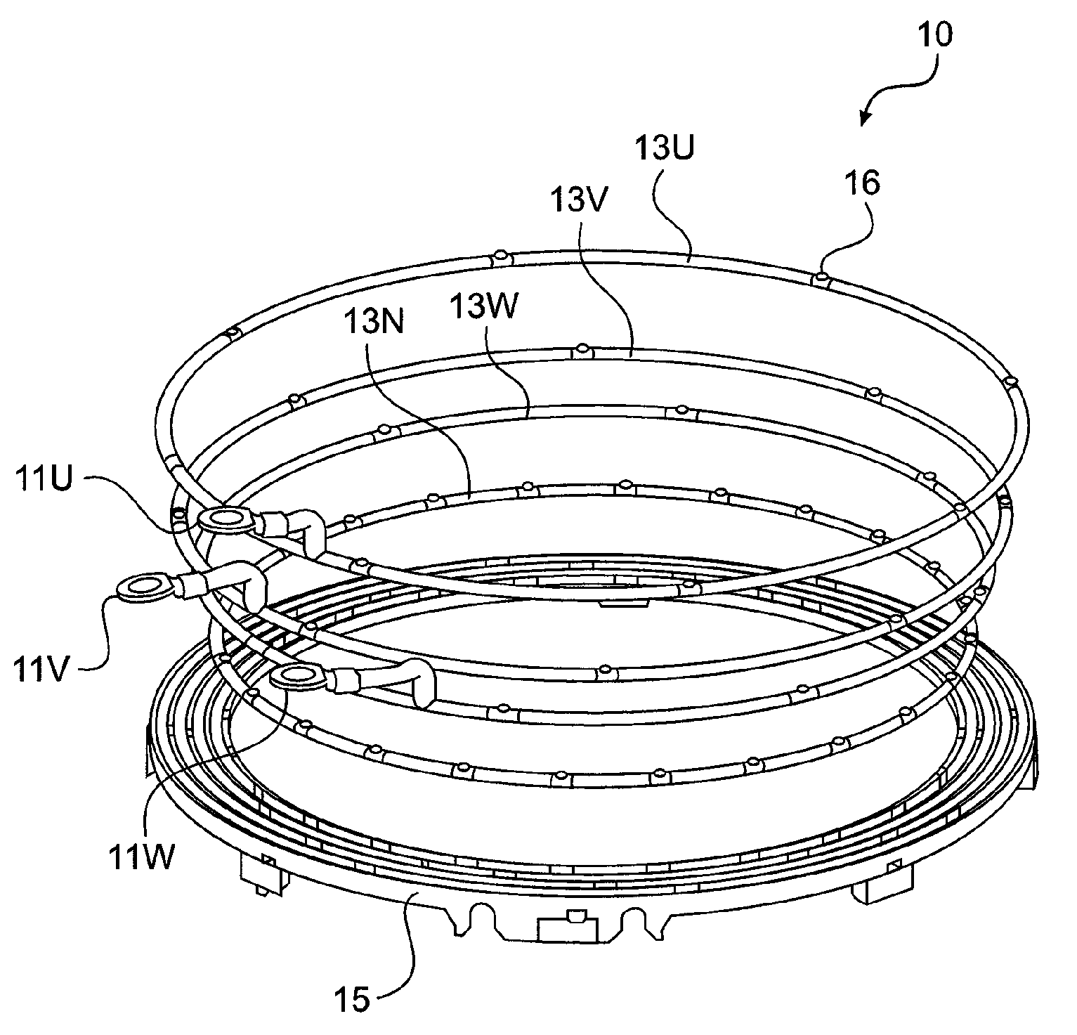
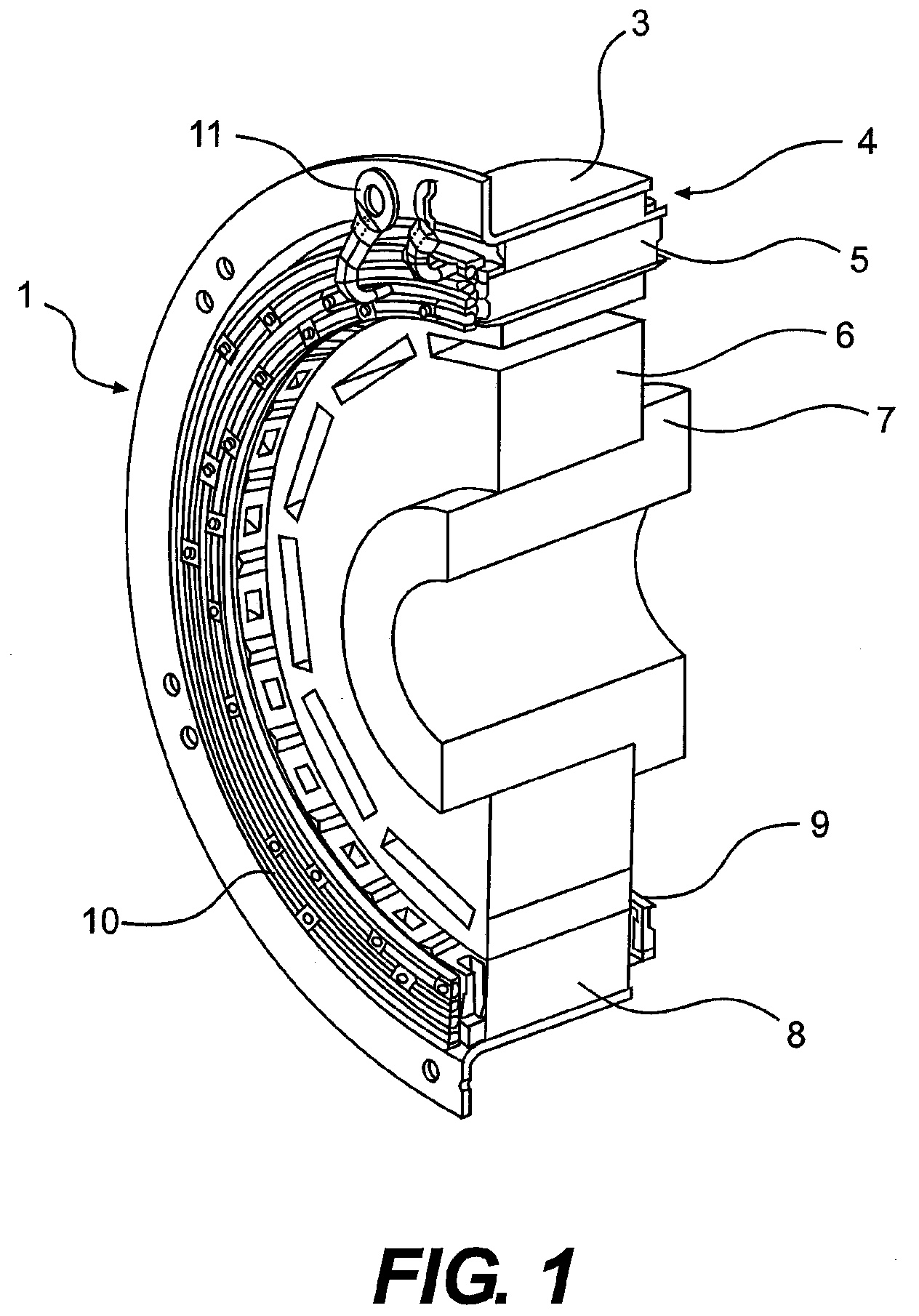
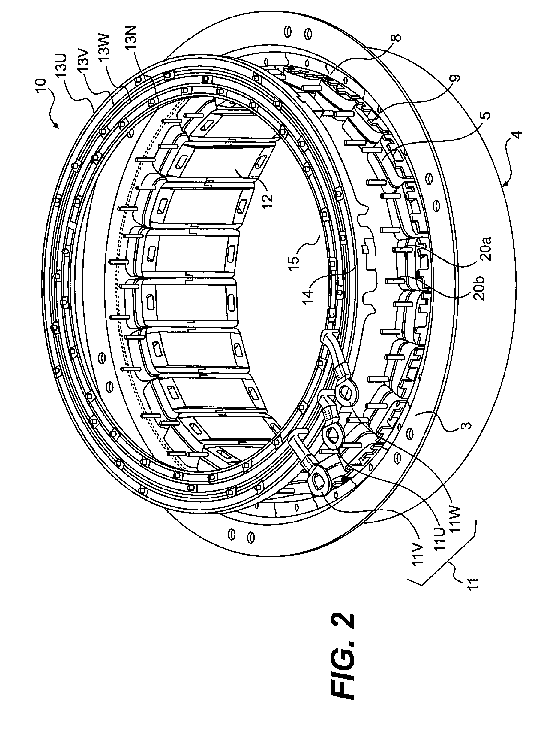
[0028]Hereinafter, the construction of the power distribution unit for a rotary electric machine according to one embodiment of the present invention will be described with reference to FIGS. 1 to 6.

[0029]First, referring to FIG. 1, explanation is made on the construction of the rotary electric machine in which the power distribution unit according to one embodiment of the present invention is used.

[0030]FIG. 1 is a cross-sectional perspective view of an essential part of a rotary electric machine in which a power distribution unit according to one embodiment of the present invention is used.

[0031]A rotary electric machine 1 is of a type used for a hybrid car. The rotary electric machine 1 as shown is of a thin type and is arranged between an engine (not shown) and a transmission (not shown). The rotary electric machine 1 includes a rotor 6, which is fitted in a shaft 7 and is coupled with a crankshaft (not shown) of the engine and the transmission through a switching device such as...


PUM


Abstract

The power distribution unit for a rotary electric machine includes a connecting ring unit that connects stator coils of the same phase. The connecting ring unit includes at least one linear conductor integrally formed in a ring-like shape, and the connecting ring unit includes a terminal section integrally formed in the linear conductor. The terminal section is constituted by a hole through which a wiring end of the stator coil is inserted and a protrusion formed in a direction of the hole to which the wiring end of the stator coil is connected. Also disclosed are a rotary electric machine includes the power distribution unit and a method for assembling a rotary electric machine.

Description

INCORPORATION BY REFERENCE[0001]The disclosure of the following priority application is herein incorporated by reference:[0002]Japanese Patent Application No. 2007-115643 (filed Apr. 25, 2007)[0003]Also, the disclosures of the following references are herein incorporated by reference:[0004]U.S. Patent Application Publication No. US 2003 / 0173842 A1 published Sep. 18, 2003[0005]U.S. Pat. No. 6,034,460.BACKGROUND OF THE INVENTION[0006]1. Field of the Invention[0007]The present invention relates to a rotary electric machine, a power distribution unit therefor, and a method for assembling rotary electric machine. More particularly, the present invention relates to a power distribution unit for a rotary electric machine with a connection ring, utilized for the connection of a stator coil of the rotary electric machine.[0008]2. Description of Related Art[0009]A rotating electric machine is disclosed in U.S. Pat. No. 6,034,460, which includes a stator having stator salient poles, three-phas...

Claims


Application Information

Patent Timeline
IPC IPC(8): H02K11/00H02K15/00
CPCY10T29/49009H02K3/522
Inventor UEDA, TOSHIAKIHOSHINO, KATSUHIROONOSE, SHINTOBA, AKIRAOBATA, KOJI
Owner HITACHI ASTEMO LTD
Why Eureka
Try Eureka