Cylinder device and method for manufacturing cylinder device

Active Publication Date: 2019-10-10
KYB CORP
View PDF0 Cites 8 Cited by
  • Summary
  • Abstract
  • Description
  • Claims
  • Application Information

AI Technical Summary

Benefits of technology

The patent is about a cylinder device that allows for easy welding of a protrusion to an outer shell and allows for the protrusion to protrude outward from a side portion of a tubular portion in a state where the bracket is fixed to the outer shell. The technical effect of this invention is the avoidance of interference between the protrusion and peripheral components in a mounting state onto a vehicle.

Problems solved by technology

However, in a state where the protrusion protrudes outward from the side portion of the tubular portion, it would be difficult to weld even though the hole for inserting the protrusion is enlarged.
The reason is that a mounting portion is connected to the front portion of the tubular portion to reduce the distance between the protrusion and the mounting portion, and thus, the mounting portion would hinder welding operation.
Therefore, in the case of performing automatically welding the outer shell on which the bracket is mounted on the outer periphery and the protrusion being set in a welding machine, there would be a need to avoid interference between the components of the machine such as a torch or an arm to drive the torch and the mounting portion, leading to a possibility of having a large-scaled welding machine to increase the cost or giving up automatic welding by the machine.

Method used


Image

  • Cylinder device and method for manufacturing cylinder device
  • Cylinder device and method for manufacturing cylinder device
  • Cylinder device and method for manufacturing cylinder device

Examples


Embodiment Construction

[0016]Hereinafter, an embodiment of the present invention will be described with reference to the drawings. Same reference numerals assigned throughout the several views indicate same components.

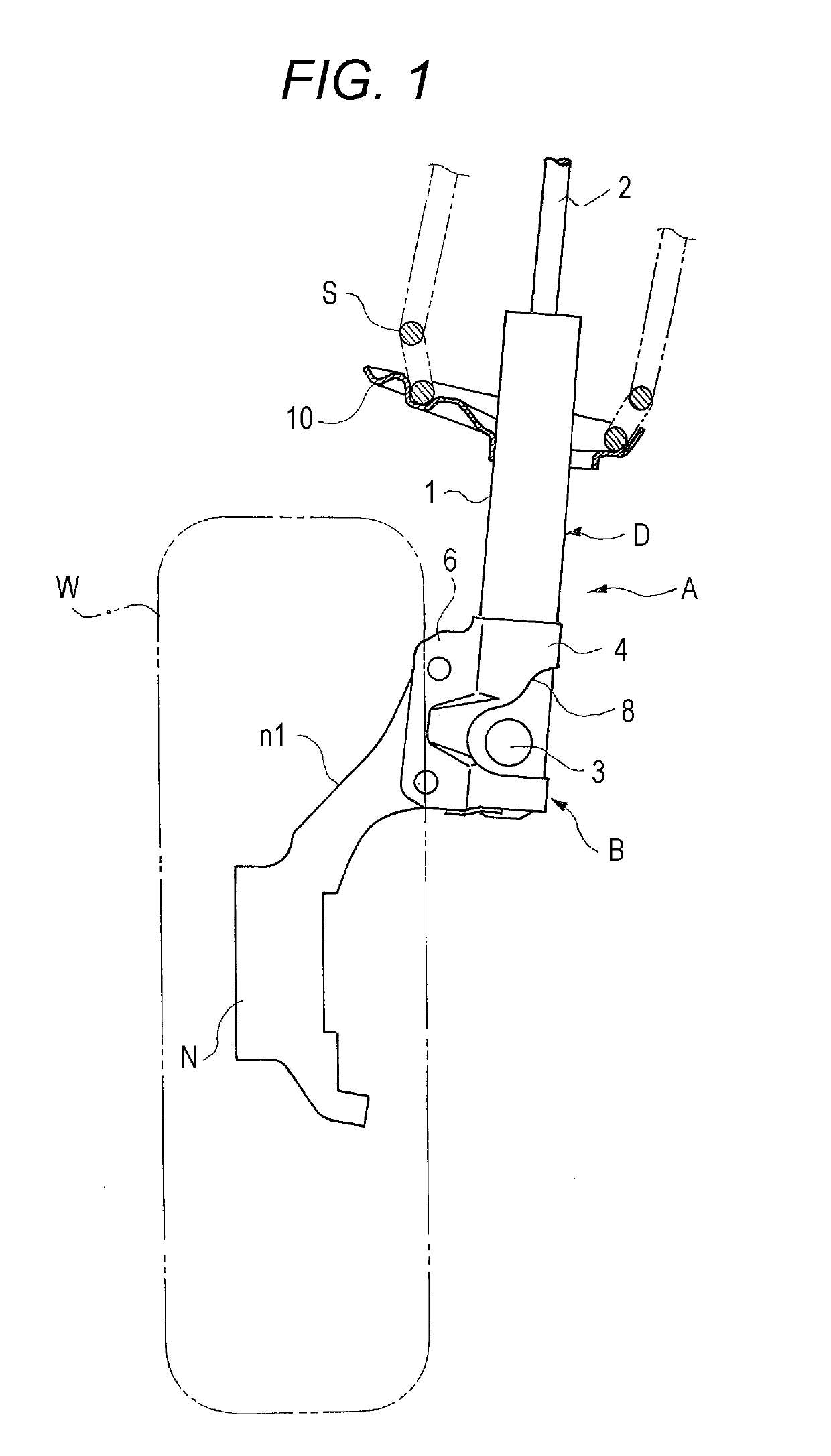
[0017]As illustrated in FIG. 1, a cylinder device according to an embodiment of the present invention is implemented as a damper A used for a strut suspension, and is used for a vehicle such as a four-wheeled automobile. The damper A includes a main body D having an outer shell 1 and a rod 2 to be inserted into the outer shell 1, a vehicle body-side mount (not illustrated) that joins the rod 2 to the vehicle body, a bracket B that joins the outer shell 1 to a wheel W, a spring receiver (not illustrated) to be attached to the vehicle body-side mount, a dish-shaped spring receiver 10 attached to an outer periphery of the outer shell 1, and a suspension spring S interposed between the two spring receivers.

[0018]More specifically, the wheel W is rotatably supported by a knuckle N, and the bracke...


PUM


Abstract

A bracket of a cylinder device includes: a tubular portion having a C-shaped cross section, holding an outer periphery of the outer shell, and having a slit in a front portion; and a pair of mounting portions and protruding outward in the radial direction from both ends of the tubular portion in the circumferential direction. The tubular portion includes a hole formed to permit insertion of the protrusion, from at least one side portion to the back portion of the tubular portion.

Description

TECHNICAL FIELD[0001]The present invention relates to a cylinder device and a method for manufacturing a cylinder device.BACKGROUND ART[0002]As disclosed in JP 2015-59574 A, a certain conventional cylinder device functions as a damper while being provided with a damping force variable valve attached to a side portion of an outer shell. The damper uses the damping force variable valve to adjust the resistance applied to the flow of the hydraulic fluid generated when the damper is expanded or compressed, enabling adjustment of levels of the damping force generated by the damper. Furthermore, the damping force variable valve can be provided at a side portion of the outer shell so as to protrude outward in a radial direction, so that the axial length of the damper is able to be reduced without sacrificing the stroke length of the damper. Therefore, this type of cylinder device can enhance mountability.[0003]Some of the cylinder devices are used in strut suspensions, specifically used as...

Claims


Application Information

Patent Timeline
IPC IPC(8): F16F9/32F16F9/54B60G13/00
CPCB60G13/005B60G13/08B60G2206/41B60G2204/129F16F2226/048B23K2101/006F16F9/3235B60G2206/8201F16F9/54F16F9/32
Inventor SHIBATA, YOSHIHIROINAGAKI, YASUHIRO
Owner KYB CORP
Why Eureka
Try Eureka