Terminal of rechargeable battery and method of manufacturing the same

Active Publication Date: 2012-01-26
ROBERT BOSCH GMBH +1
View PDF11 Cites 21 Cited by
  • Summary
  • Abstract
  • Description
  • Claims
  • Application Information

AI Technical Summary

Benefits of technology

[0013]In the terminal of the rechargeable battery and the method of manufacturing the same according to an embodiment, a conductor formed of copper or copper alloy is provided on a terminal plate formed of aluminum or aluminum alloy. Also, a terminal post formed of copper or copper alloy is coupled to the conductor formed of copper or copper alloy. Thus, the terminal post formed of copper or copper alloy and the conductor formed of copper or copper alloy may be easily welded to each other.
[0014]The terminal of the rechargeable battery according to an embodiment is adequate for the negative terminal. That is, the negative electrode plate of the electrode assembly is formed of copper or copper alloy, and also the negative electrode collector welded to the negative electrode plate is formed of copper or copper alloy. Furthermore, the negative electrode terminal post coupled to the negative electrode collector is formed of copper or copper alloy. Since the bus bar (a member that connects a plurality of rechargeable batteries to each other in series or in parallel) coupled to the negative terminal plate is generally formed of aluminum or aluminum alloy, the terminal plate is formed of aluminum or aluminum alloy to easily weld the terminal plate thereto.
[0016]However, according to the embodiment, since the conductor formed of copper or copper alloy is provided on the negative terminal plate formed of aluminum or aluminum alloy, the negative terminal post formed of copper or copper alloy and the conductor formed of copper or copper alloy may be easily welded to each other.
[0017]In addition, since the conductor is formed using the plating process or the diffusion-welding process, the coupling force between the conductor and the terminal plate may be improved. That is, the conductor is not separated or exfoliated from the terminal plate. Also, when a surface of the terminal plate is roughened and the conductor is formed on the roughened surface through the plating process, the coupling force between the terminal plate and the conductor may be further improved.
[0018]Furthermore, since the conductor has a thickness of about 1 mm or more, the sufficient welding region may be secured between the terminal post and the conductor. Therefore, the welding strength between the terminal post and the conductor may be further improved.

Problems solved by technology

Thus, it is difficult to weld the negative terminal post formed of copper or copper alloy to the negative terminal plate formed of aluminum or aluminum alloy.

Method used


Image

  • Terminal of rechargeable battery and method of manufacturing the same
  • Terminal of rechargeable battery and method of manufacturing the same
  • Terminal of rechargeable battery and method of manufacturing the same

Examples


Embodiment Construction

[0025]Example embodiments will now be described more fully hereinafter with reference to the accompanying drawings; however, they may be embodied in different forms and should not be construed as limited to the embodiments set forth herein. Rather, these embodiments are provided so that this disclosure will be thorough and complete, and will fully convey the scope of the invention to those skilled in the art.

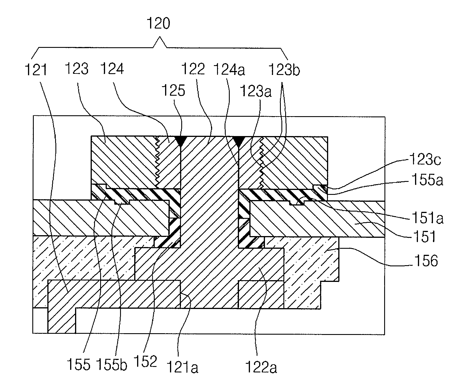
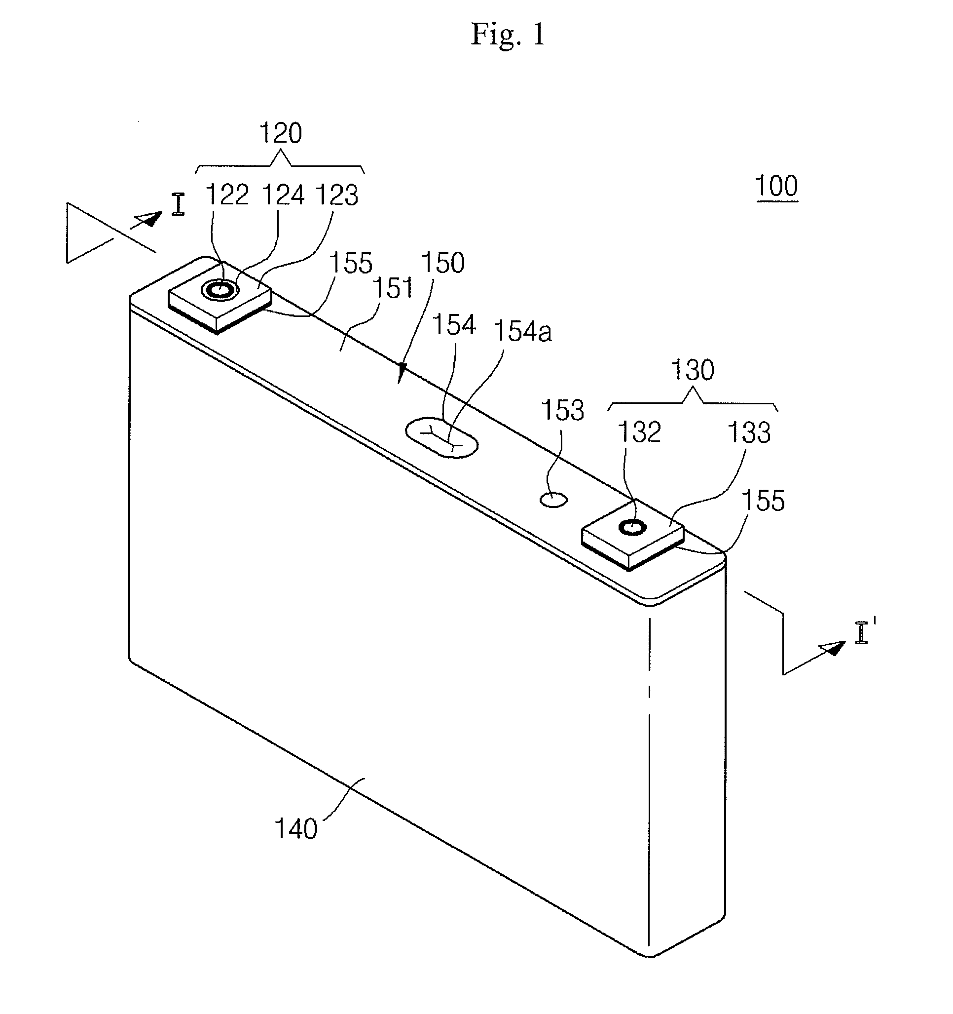
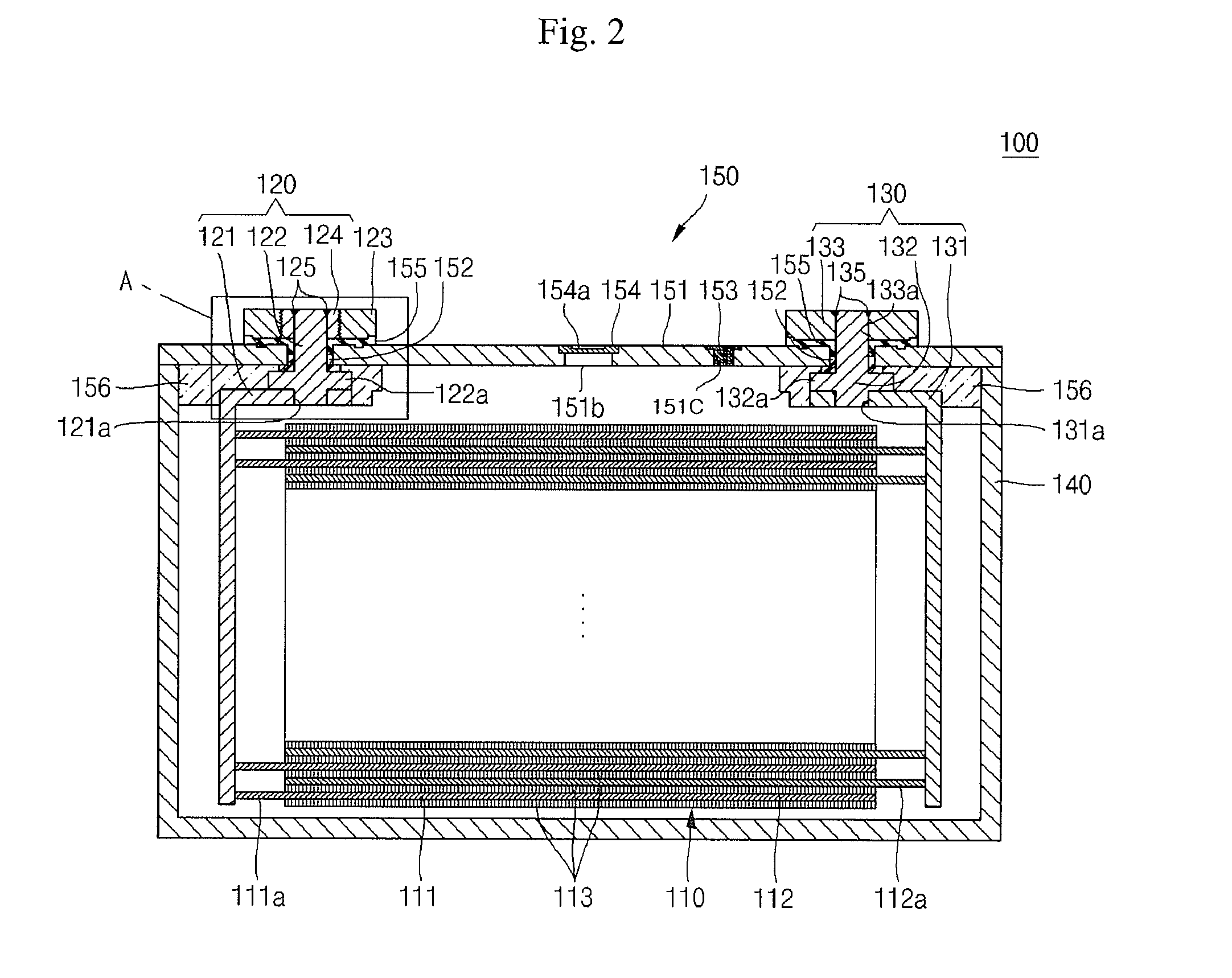
[0026]FIG. 1 illustrates a perspective view of a rechargeable battery according to an embodiment. FIG. 2 illustrates a sectional view taken along line I-I′ of FIG. 1. FIG. 3A illustrates an enlarged sectional view of a portion A of FIG. 2, and FIGS. 3B and 3C illustrate enlarged sectional views of other embodiments of the present invention.

[0027]Referring to FIGS. 1 through 3, a rechargeable battery 100 according to an embodiment includes an electrode assembly 110, a first terminal 120, a second terminal 130, a case 140, and a cap assembly 150.

[0028]A thin plate- or film-shaped ...


PUM


Abstract

A rechargeable battery including a case; a cap plate on the case; a terminal post protruding from the cap plate; a terminal plate coupled to the terminal post, wherein the terminal plate includes a body having an opening; and a conductor within the opening and coupled to the body, wherein the conductor substantially surrounds a circumference of the terminal post.

Description

CROSS-REFERENCE TO RELATED APPLICATIONS[0001]This application claims priority to and the benefit of U.S. Provisional Application 61 / 366,396 filed Jul. 21, 2010, in the United States Patent Office, the entire content of which is incorporated herein by reference.BACKGROUND[0002]1. Field[0003]Embodiments relate to a terminal of a rechargeable battery and a method of manufacturing the same.[0004]2. Related Art[0005]Generally, rechargeable batteries are capable of being charged and discharged unlike primary batteries that are not capable of being recharged. In the case of a low capacity battery in which one battery cell is packaged into a pack shape, the low capacity battery may be used as a power source for various portable small electronic devices such as mobile phones, camcorders, etc. In case of a high capacity battery in which several tens of battery cells are connected in serial or in parallel, the high capacity battery may be used as a power source for driving motors such as elect...

Claims


Application Information

Patent Timeline
IPC IPC(8): H01M2/30H01M50/103
CPCH01M2/02H01M2/0473H01M2/1016Y02T10/7011H01M10/04H01M10/052H01M2/307Y02E60/10H01M50/15H01M50/561Y02P70/50H01M10/058H01M50/103Y02T10/70
Inventor BYUN, SANGWONSHIN, YOUNGKEECHANG, JINHWANJEONG, MYUNGJINCHOI, SANGSHINOH, JEONGWONCHOI, SOOSEOK
Owner ROBERT BOSCH GMBH
Why Eureka
Try Eureka