Imaging lens

a technology of imaging lens and lens body, applied in the field of compound imaging lens, can solve the problems of large astigmatism of about 0.1 mm, aberration that unfortunately requires further compensation

Inactive Publication Date: 2008-10-30
SEIKO PRECISION CO LTD
View PDF4 Cites 23 Cited by
  • Summary
  • Abstract
  • Description
  • Claims
  • Application Information

AI Technical Summary

Benefits of technology

[0015]H is defined as the effective radius of the surface of the third lens facing the image surface,

Problems solved by technology

However, the imaging lens discussed in the Unexamined Japanese Patent Application KOKAI Publication recited above has insufficient aberration compensation, resulting in a large astigmatism of about 0.1 mm.
This aberration unfortunately requires further compensation for use in a camera having a high quality image sensor.

Method used


Image

  • Imaging lens
  • Imaging lens
  • Imaging lens

Examples


first exemplary embodiment

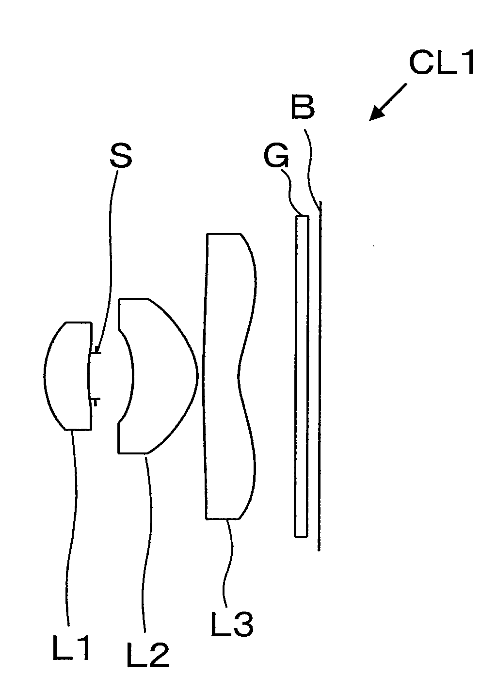
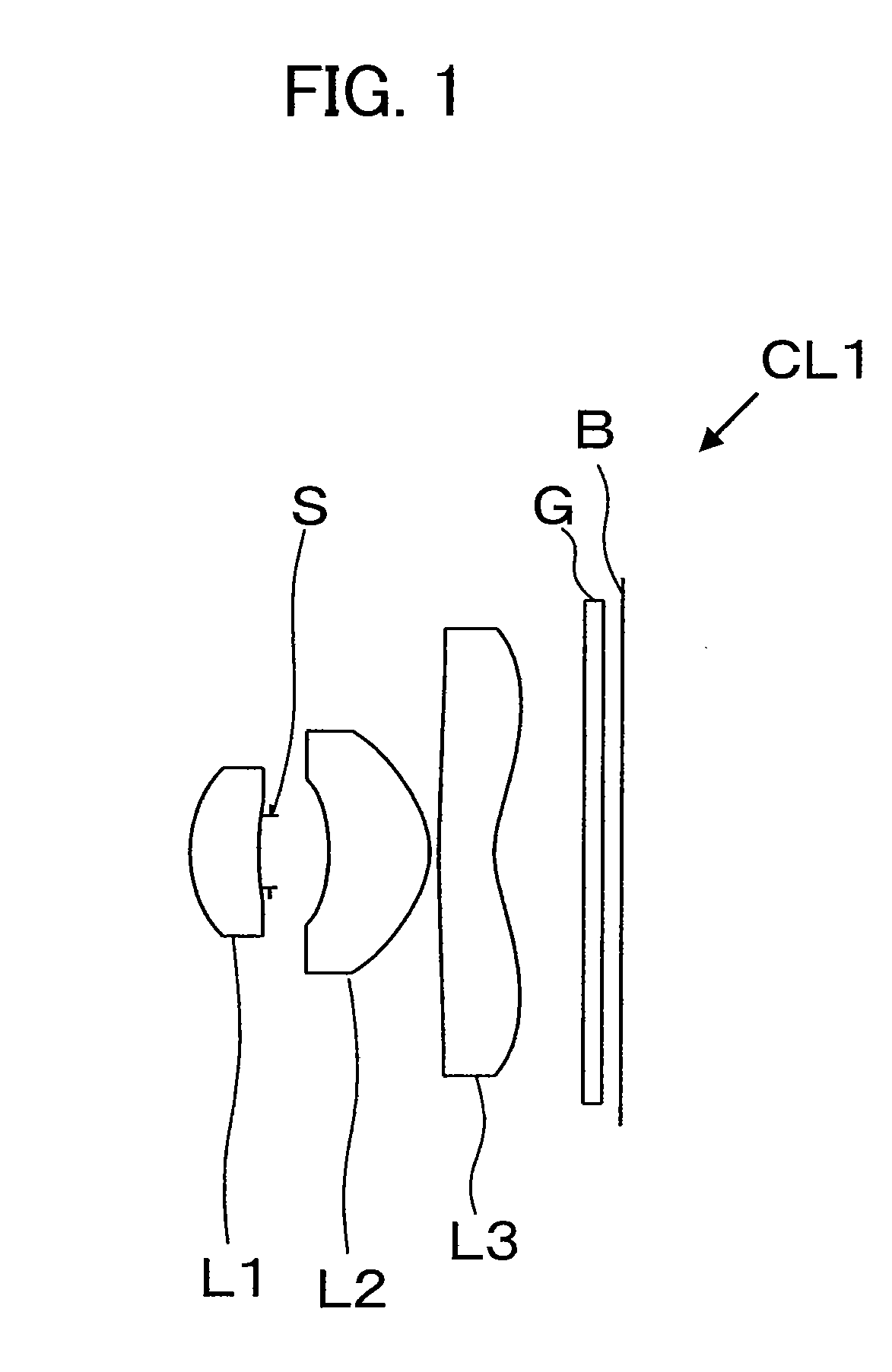
[0057]The data defining lens elements of an imaging lens CL1 according to a first exemplary embodiment is presented in Table 2. In Table 2, “curvature radius r” is defined as the curvature radius of each lens surface; “distance d” is defined as the distance from the No. i surface (lens surface or element surface) to the No. i+1 surface; “refractive index nd” is the refractive index of the material at the wavelength of the Fraunhofer d curve (587.6 nm); and “Abbe number vd” is the Abbe number with respect to the d curve wavelength.

[0058]Hereinafter for brevity, “Fraunhofer line wavelength” may be referred to as “line,” e.g., “Fraunhofer C curve wavelength” may be referred to as “C curve,” etc.

TABLE 2CurvatureDistanceRefractiveAbbeNo.Radius rdIndex ndNumber νdDescription00Infinity11.45240.7661.5311556.0first lens23.36000.127300.658aperture4−1.87281.1221.5311556.0second lens5−0.89530.167.11650.6151.5311556.0Third lens71.08891800.211.516864.2filter900.216

[0059]The numbers (No.) in Table...

second exemplary embodiment

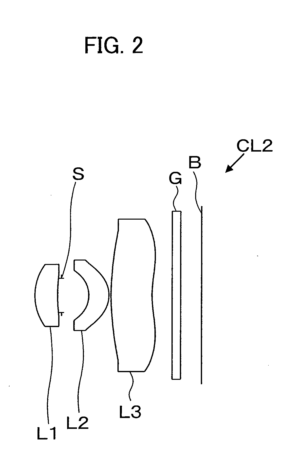
[0067]The data defining lens elements of an imaging lens CL2 according to a second exemplary embodiment is presented in Table 4. The definitions of terms and numbers (No.) in Table 4 are the same as those in Table 2.

TABLE 4CurvatureRefractiveAbbeNo.Radius rDistance dIndex ndNumber νdDescription00Infinity11.29960.5661.5311556.0first lens24.12870.089300.684aperture4−0.68560.51.5311556.0second lens5−0.71650.0563.74021.021.5311556.0third lens72.35500.5800.211.516864.2filter900.523

[0068]The parameters defining a first lens L1 through a third lens L3 of the imaging lens CL2, i.e., a conic constant k and asphericity coefficients α4, α6, α8, α10, and α12, are presented in Table 5. The numbers (No.) in Table 5 are the same as those in Table 4, and the definitions of the asphericity coefficients α4, α6, α8, α10, and α12 are the same as those of the imaging lens CL1.

TABLE 5No.kα4α6α8α10α121−0.3216416710.0190978740.105187067−0.3652037350.662317131−0.480016954248.31222223−0.018860323−1.114824549...


PUM


Abstract

An imaging lens has a compact shape and sufficiently compensates for various aberrations.
The imaging lens includes a first lens, a second lens, and a third lens disposed sequentially, with the first lens toward an object. The conditions “0.5H<T0<0.7H,”“2<φr4/φ<2.5,” and “0.15<φr5/φ<0.3” are satisfied, where: H is the effective radius of the surface of the third lens facing an image surface; T0 is the distance between the optical axis and a point on a line parallel to the optical axis and normal to the surface of the third lens facing the image surface; φ is the combined refractive power of the imaging lens; φr4 is the refractive power of the surface of the second lens facing the image surface; and φr5 is the refractive power of the surface of the third lens facing the object.

Description

BACKGROUND OF THE INVENTION[0001]1. Field of the Invention[0002]The present invention relates to a compound imaging lens including three lens elements.[0003]2. Description of the Related Art[0004]In recent years, the advancement of miniature solid-state image sensors for mobile cameras mounted in applications such as mobile phones has resulted in the use of solid-state image sensors having pixels 3 μm or smaller in size. An imaging lens requires three or more lens elements to practically accommodate solid-state image sensors of such extremely small pixel sizes. Such optical systems require corrections to sufficiently compensate for various aberrations.[0005]Unexamined Japanese Patent Application KOKAI Publication No. 2006-308789 discusses a known example of an imaging device using three lens elements.[0006]However, the imaging lens discussed in the Unexamined Japanese Patent Application KOKAI Publication recited above has insufficient aberration compensation, resulting in a large as...

Claims


Application Information

Patent Timeline
Patent Type & Authority Applications(United States)
IPC IPC(8): G02B9/12
CPCG02B9/12G02B13/0035
Inventor NIO, JUNICHI
Owner SEIKO PRECISION CO LTD
Why Eureka
Try Eureka