Pre-Synchronization Method for Hard Handovers in Wireless Networks

a wireless network and pre-synchronization technology, applied in the field of wireless cellular communications, can solve the problems of affecting the cost of both user equipment and base stations, user equipment typically performing a hard handover, and requiring some complexity, so as to reduce the interruption time of handover, reduce the latency of rach/ul synchronization, and simple and efficient method

Active Publication Date: 2008-10-30
APPLE INC
View PDF4 Cites 146 Cited by
  • Summary
  • Abstract
  • Description
  • Claims
  • Application Information

AI Technical Summary

Benefits of technology

[0011]This invention is a pre-synchronization method in which the source base station chooses a signature for the user equipment to use in the target base station for RACH access and instructs the user equipment to perform RACH access and return to the current base station before a handover command is issued by the source base station. This causes parallel execution of the UL synchronization process with the context transfer process among the two base stations. This invention thus reduces handover interruption time.
[0012]Other solutions simply try to reduce the RACH / UL synchronization latency. Our proposal causes the latency to happen in parallel with other latency. This offers a simple and efficient method for pre-synchronization during handovers. This technique requires no signification additional overhead.

Problems solved by technology

This has the benefit of providing no interruption time, but requires some complexity which impacts the cost of both user equipment and base station.
In cellular networks where the user equipment can be served by only one base station at a time, the user equipment typically performs a hard handover when transitioning from one cell to another.
This results in some unavoidable interruption time.
The main cause for handover interruption time is the user equipment must complete any final formalities with the source base station and achieve UL synchronization and initial allocation with the target base station.

Method used


Image

  • Pre-Synchronization Method for Hard Handovers in Wireless Networks
  • Pre-Synchronization Method for Hard Handovers in Wireless Networks
  • Pre-Synchronization Method for Hard Handovers in Wireless Networks

Examples


first embodiment

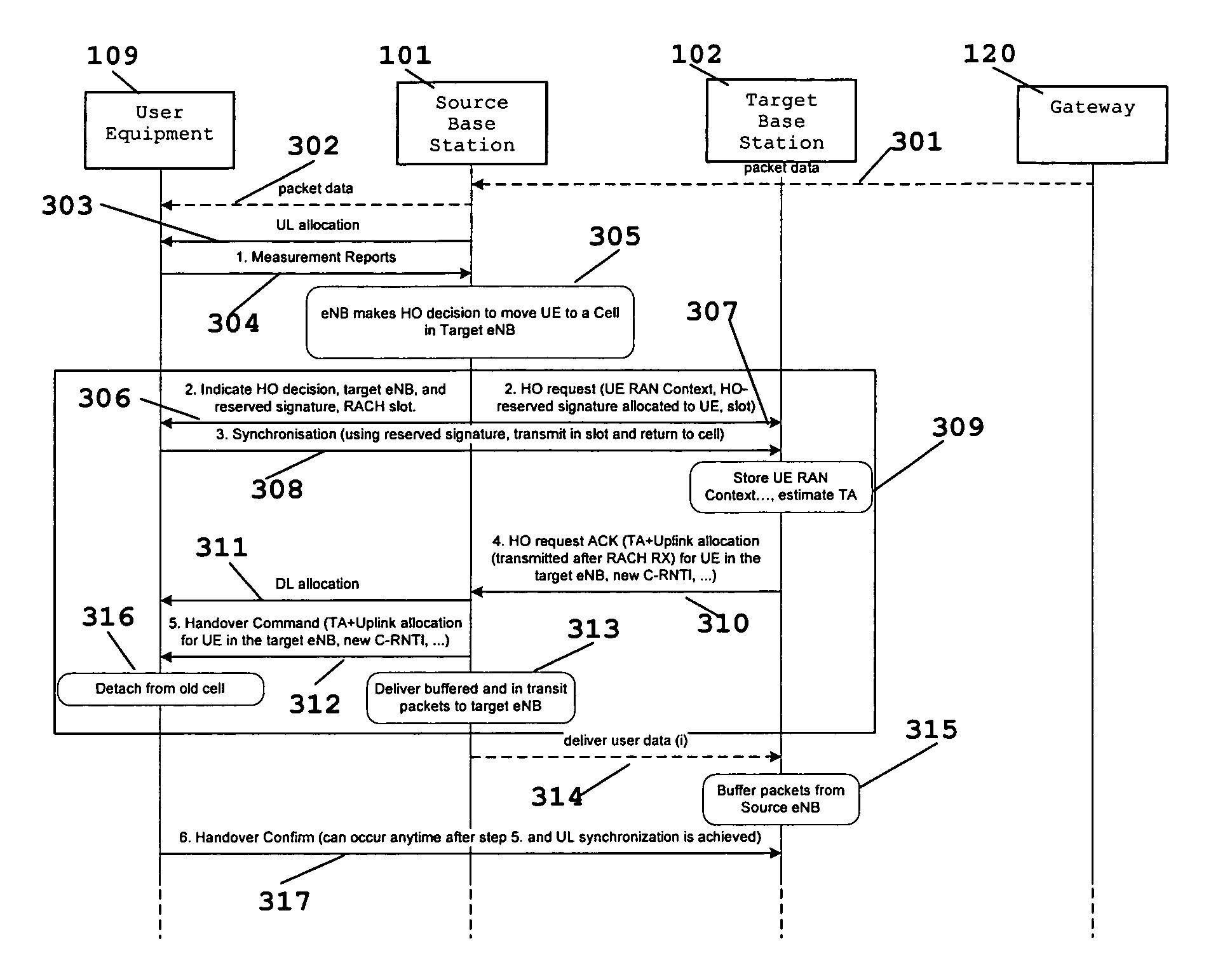
[0026]FIG. 3 illustrates the communications process according to this invention. Initially packet data from gateway 120 is transmitted to base station 101 (step 301) the current base station for transmission to user equipment 109 (step 302). In step 302, base station 101 transmits a measurement control signal to user equipment 109. Base station 101 transmits a UL allocation signal to user equipment 109 (step 303). User equipment 109 responds with measurement reports (step 304) to base station 101. Base station 101 makes the handover decision (step 305). Base station 101 then sends a handover indication to user equipment 109 (step 306) with the reserved signature to use and the RACH slot to use with base station 102. Base station 101 also initiates a handover request to base station 102 in parallel (step 307). This also includes the communications parameters. Base station 101 knows the RACH slot when user equipment 109 accesses base station 102 and does not schedule it near that slot...

second embodiment

[0032]FIG. 4 illustrates this method which uses pre-synchronization based upon contention based RACH access. The pre-synchronization method with contention based access is identical to the contention-free access method illustrated in FIG. 3. As previously illustrated in FIG. 3, the UL synchronization process happens in parallel with the context transfer process. However, there are certain differences because of RACH procedure differences, and there is no longer a need that any signatures be pre-available at the source base station. This method is invoked when no handover reserved signature from target cell is available.

[0033]Initially packet data from gateway 120 is transmitted to base station 101 (step 401) the current base station for transmission to user equipment 109 (step 402). In step 402, base station 101 transmits a measurement control signal to user equipment 109. Base station 101 transmits a UL allocation signal to user equipment 109 (step 403). User equipment 109 responds...


PUM


Abstract

A pre-synchronization method in which the source cell chooses a signature for the user equipment (mobile) to use in the target cell for RACH access, and instructs the user equipment to perform RACH access and return to the current cell before a handover command (break command) is issued. This causes parallel execution of the UL synchronization process with the context transfer process among the two base stations.

Description

CLAIM OF PRIORITY[0001]This application claims priority under 35 U.S.C. 119(e) (1) to U.S. Provisional Application No. 60 / 914,937 filed Apr. 30, 2007.TECHNICAL FIELD OF THE INVENTION[0002]The technical field of this invention is wireless cellular communications and in particular to hard handovers in asynchronous networks.BACKGROUND OF THE INVENTION[0003]Wireless cellular communication networks incorporate a number of mobile user equipments (UEs) and a number of NodeBs. A NodeB is generally a fixed station and may also be called a base transceiver system (BTS), an access point (AP), a base station (BS) or some other equivalent terminology. NodeB functionality evolves as improvements of networks are made, so a NodeB is sometimes also referred to as an evolved NodeB (eNB). In general NodeB hardware is fixed and stationary. In contrast user equipment hardware is generally portable. User equipment, commonly known to as a terminal or a mobile station, may be fixed or mobile device and may...

Claims


Application Information

Patent Timeline
Patent Type & Authority Applications(United States)
IPC IPC(8): H04Q7/00H04J3/06H04W36/08
CPCH04W36/0072
Inventor KANGUDE, SHANTANUBERTRAND, PIERREXHAFA, ARITON E.
Owner APPLE INC
Why Eureka
Try Eureka