Distributed Antenna Wlan Access-Point System and Method

a distributed antenna and access point technology, applied in the field of wlan infrastructure, can solve the problems of mutual interference between neighboring neighbors, general limitation of existing wlan infrastructure systems, and inefficient increase of ap density in order to increase throughput, etc., and achieve the effect of being ready to implemen

Inactive Publication Date: 2008-10-30
STELLARIS
View PDF14 Cites 84 Cited by
  • Summary
  • Abstract
  • Description
  • Claims
  • Application Information

AI Technical Summary

Benefits of technology

[0014]The present invention relates to a WLAN AP system with distributed antenna units which is capable of communicating with several WLAN clients simultaneously over the same RF chan

Problems solved by technology

It is noted, however, that one of the limitations of prior art systems is that such increase of AP density in order to increase throughput is not efficient, and reaches a saturation point wherein adding more APs does not add further capacity.
A significant general limitation of existing WLAN infrastructure systems appears whenever such a system comprises several prior art APs.
In such a ca

Method used


Image

  • Distributed Antenna Wlan Access-Point System and Method
  • Distributed Antenna Wlan Access-Point System and Method
  • Distributed Antenna Wlan Access-Point System and Method

Examples


Embodiment Construction

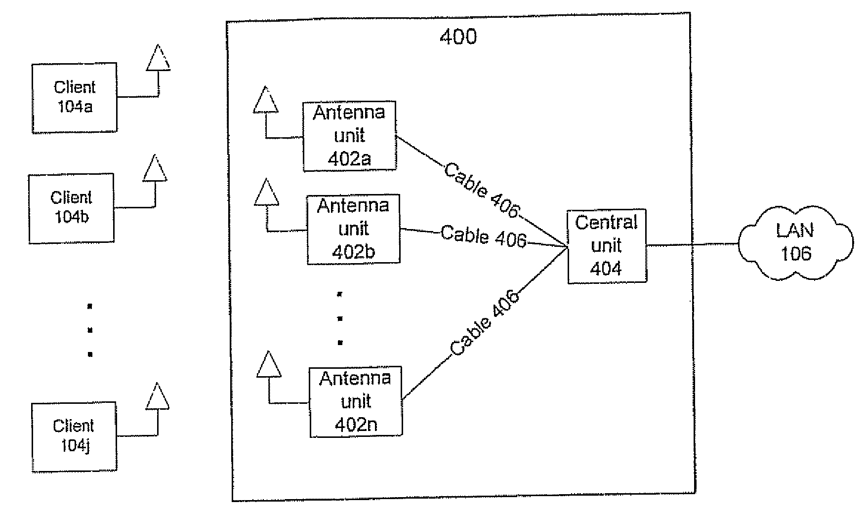
[0031]The present invention is of a WLAN AP infrastructure with distributed antenna units and of a corresponding method that provides a novel WLAN infrastructure. The preferred embodiments of the present invention are discussed in detail below. It is to be understood that the present invention is not limited to the details of construction, arrangement, and composition of the components of the system, and is not limited in its application to the details of the order or sequence of steps of operation or implementation of the corresponding method set forth in the following description, drawings, or examples. While specific steps, configurations and arrangements are discussed, it is to be understood that this is done for illustrative purposes only. A person skilled in the relevant art will recognize that other steps, configurations and arrangements can be used without departing from the spirit and scope of the present invention.

[0032]Construction, arrangement, and, composition of the sy...


PUM


Abstract

A wireless local area network (WLAN) access point (AP) system comprises a first plurality of distributed remote antenna units operative to transmit and receive RF signals and a central WLAN beam-forming unit connected to each distributed remote antenna unit and operative to provide communication between the antenna units and a second plurality of wireless clients. The WLAN AP system can be used for simultaneous communications with the wireless clients over the same radio frequency (RF) channel while avoiding mutual interferences.

Description

FIELD AND BACKGROUND OF THE INVENTION[0001]The present invention relates to a WLAN infrastructure and more specifically to a WLAN access-point (AP) system with distributed antenna units that is capable of communicating with several WLAN clients simultaneously over the same radio-frequency (RF) channel.[0002]A block diagram example of a previous art WLAN infrastructure system is illustrated in FIG. 1. A prior art system 100 includes one or several Access Points (AP) 102a-n that serve many wireless clients 104a-j. APs 102a-n are connected to the local area network (LAN) of an organization 106. The APs are typically connected to the LAN using 100 Mbps Ethernet protocol over CAT5 cables. A system with a small service area and low traffic requirements may comprise a single AP, but in order to achieve large coverage area and / or high traffic, several APs 102 are required, as explained below. It is noted, however, that one of the limitations of prior art systems is that such increase of AP ...

Claims


Application Information

Patent Timeline
IPC IPC(8): H04Q7/24H04L12/28H04W88/08
CPCH01Q1/2291H01Q21/28H04W88/085
Inventor MUSHKIN, MORDECHAIRAPHAELI, DAN
Owner STELLARIS
Why Eureka
Try Eureka