Network device and connection module thereof

a network device and connection module technology, applied in the direction of coupling device details, coupling device connection, connection contact member material, etc., can solve the problems of emi (electro-magnetic interference), design cannot meet the requirement of microminiaturization of electronic devices, and affect the efficiency of the whole system, etc., to achieve the effect of easy assembly

Inactive Publication Date: 2008-10-30
DELTA ELECTRONICS INC
View PDF2 Cites 2 Cited by
  • Summary
  • Abstract
  • Description
  • Claims
  • Application Information

AI Technical Summary

Benefits of technology

[0010]In view of the foregoing, an object of the invention is to provide a network device and a connection module thereof that can integrate the connector and the network element so as to achieve microminiaturization, simplify the circuit layout and prevent EMI.
[0017]As mentioned above, the network element and the connection module of the invention are integrated on one circuit board. Thus, the network device and connection module of the invention can be easy assembled and prevent the EMI.

Problems solved by technology

This design can not meet the requirement of microminiaturization of electronic apparatuses.
Furthermore, there will be noises produced when analog signals are transformed to digital signal, which affects the efficiency of the whole system and results to the EMI (Electro-Magnetic Interference).
Nowadays, the connector 11 and the network element 12 must be designed separately to prevent EMI, hence increasing the complexity of the manufacturing process and the manufacturing cost.

Method used


Image

  • Network device and connection module thereof
  • Network device and connection module thereof
  • Network device and connection module thereof

Examples


Embodiment Construction

[0023]The present invention will be apparent from the following detailed description, which proceeds with reference to the accompanying drawings, wherein the same references relate to the same elements.

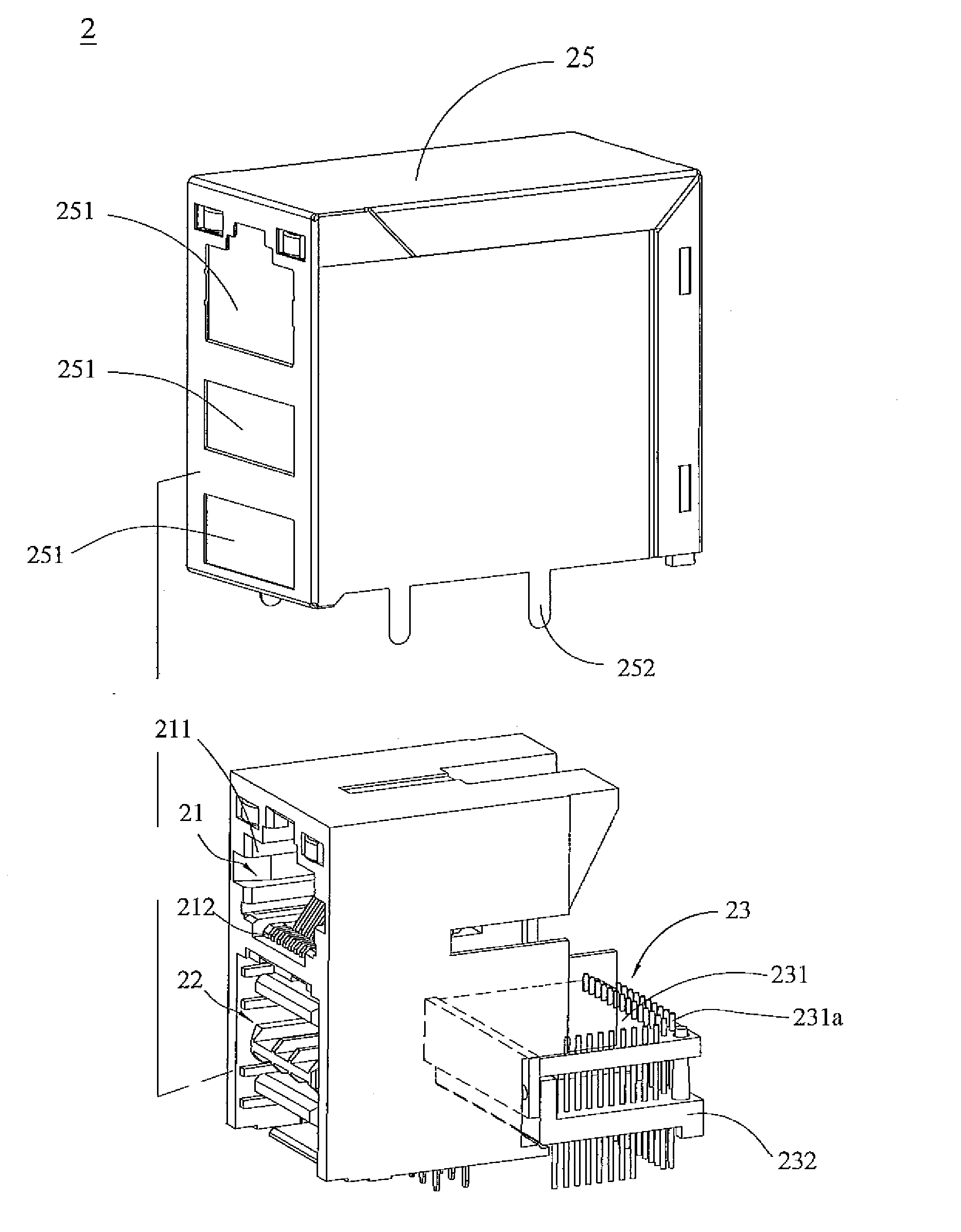
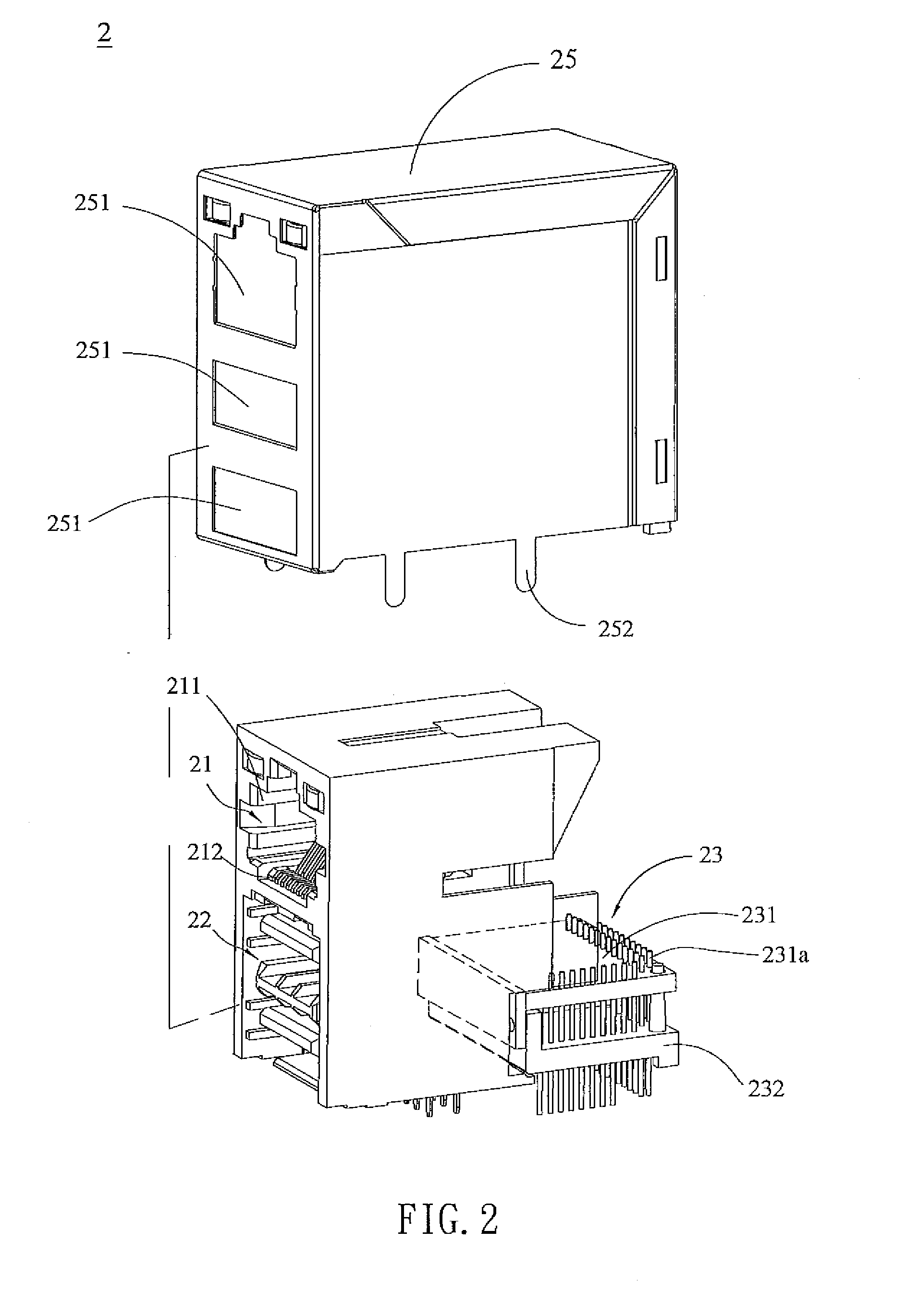
[0024]FIG. 2 is an exploded diagram of a connection module 2 of an embodiment of the invention. FIG. 3 is a schematic view of partial components shown in FIG. 2. With reference to FIG. 2 and FIG. 3, the connection module 2 of the invention includes a first connector 21, a second connector 22, a network element 23, a circuit board 24 and a housing 25. The first connector 21, the second connector 22 and the network element 23 are all disposed on the circuit board 24. The first connector 21 and the second connector 22 are disposed to a first side of the circuit board 24, and the network element 23 is disposed to a second side of the circuit board 24.

[0025]In the embodiment, the first connector 21 includes a connection hole 211 and a plurality of transmission terminals 212 disposed in the...


PUM


Abstract

A connecting module includes at least a connector, a circuit board, a network element and a housing. The connector is electrically connected to a first side of the circuit board. The network element is electrically connected to a second side of the circuit board. The connector and the network element are accommodated in the housing.

Description

CROSS REFERENCE TO RELATED APPLICATIONS[0001]This Non-provisional application claims priority under 35 U.S.C. §119(a) on Patent Application No(s). 096114953 filed in Taiwan, Republic of China on Apr. 27, 2007, the entire contents of which are hereby incorporated by reference.BACKGROUND OF THE INVENTION[0002]1. Field of Invention[0003]The invention relates to a network device and a connector and, in particular, to a network device and a connection module thereof integrating a network chip and a connector.[0004]2. Related Art[0005]Due to the fast development of information technology, computers are widespread used. In addition, under the fast development of Internet technology, computers can rapidly obtain required information and provide various information services through Internet. Therefore, it has been a trend of the information age to connect computers or peripheral apparatuses through network.[0006]As shown in FIG. 1, a conventional network device 1 includes a connector 11, a n...

Claims


Application Information

Patent Timeline
Patent Type & Authority Applications(United States)
IPC IPC(8): H01R4/66
CPCH01R13/6658H01R23/6873H01R24/62H01R13/6594
Inventor HSU, HAN-CHENG
Owner DELTA ELECTRONICS INC
Why Eureka
Try Eureka