Industrial Robot

a robot and industrial technology, applied in the field of industrial robots, can solve the problems of deteriorating the motion performance of industrial robots, increasing the cost of use forms, and taking a long time to change the use forms

Inactive Publication Date: 2008-11-06
KOWA CO LTD
View PDF6 Cites 37 Cited by
  • Summary
  • Abstract
  • Description
  • Claims
  • Application Information

AI Technical Summary

Benefits of technology

[0010]An industrial robot of the present invention includes a base for installation, a first arm, a second arm, a third arm, a wire feeder, a welding torch, and a torch cable. The first arm rotates with respect to the base. The second arm pivots with respect to the first arm. The third arm pivots with respect to the second arm. The torch cable is coupled to the wire feeder and feeds a welding wire to the welding torch. The wire feeder is provided to the second arm and is rotatable around a rotation axis. In this structure, a position in which the wire feeder is provided is common in a robot used in a state in which it is mounted on a floor and a robot used in a state in which it is mounted on a ceiling. Then, by rotating the wire feeder, floor-mounted use and ceiling-mounted use become possible.

Problems solved by technology

Thus, it takes a time to change the use forms, and the cost therefor rises.
Such a configuration deteriorates the motion performance of the industrial robot and adversely affects the approaching performance to a welding work and a jig for fixing the welding work.

Method used


Image

  • Industrial Robot
  • Industrial Robot
  • Industrial Robot

Examples


Embodiment Construction

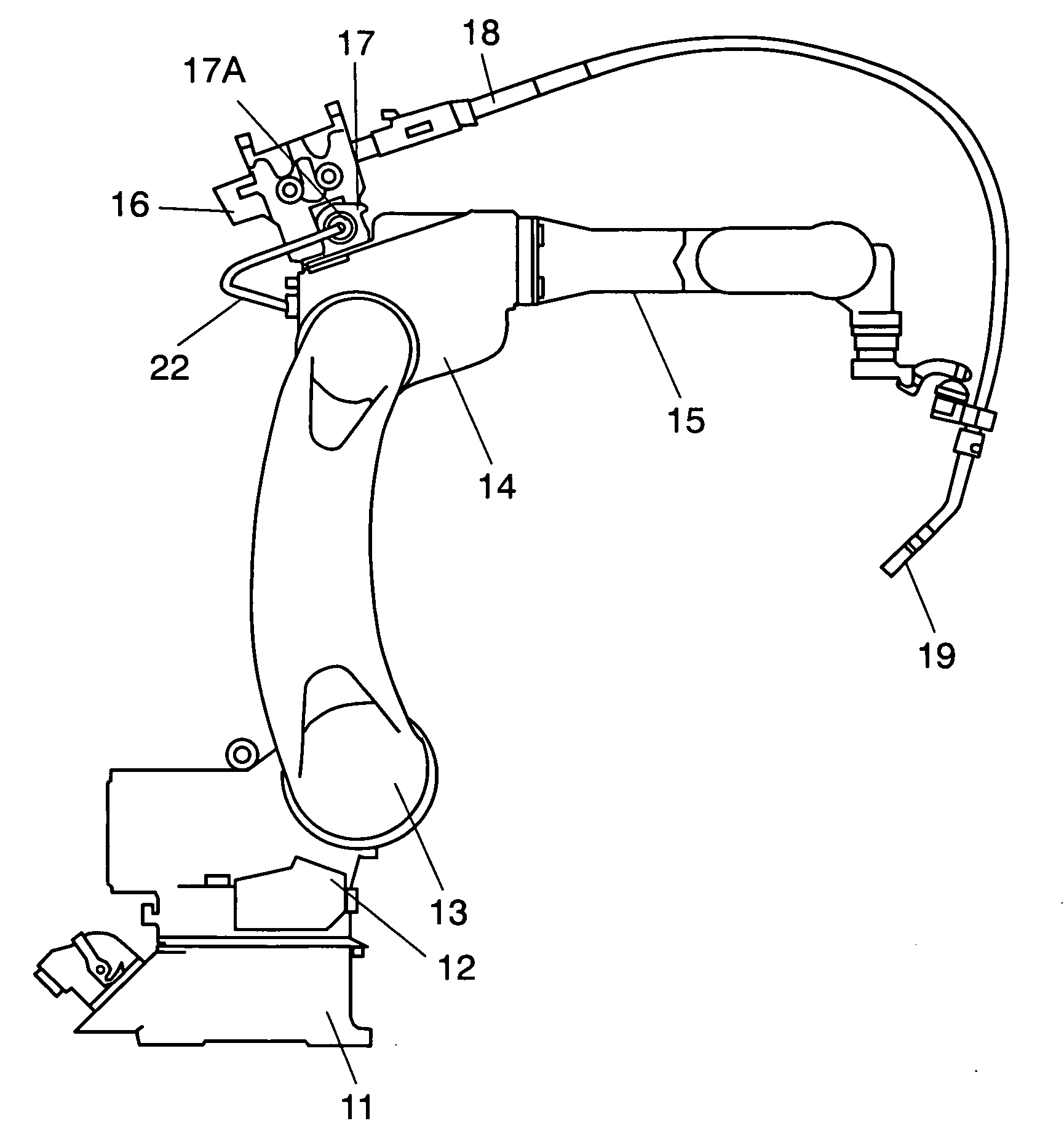
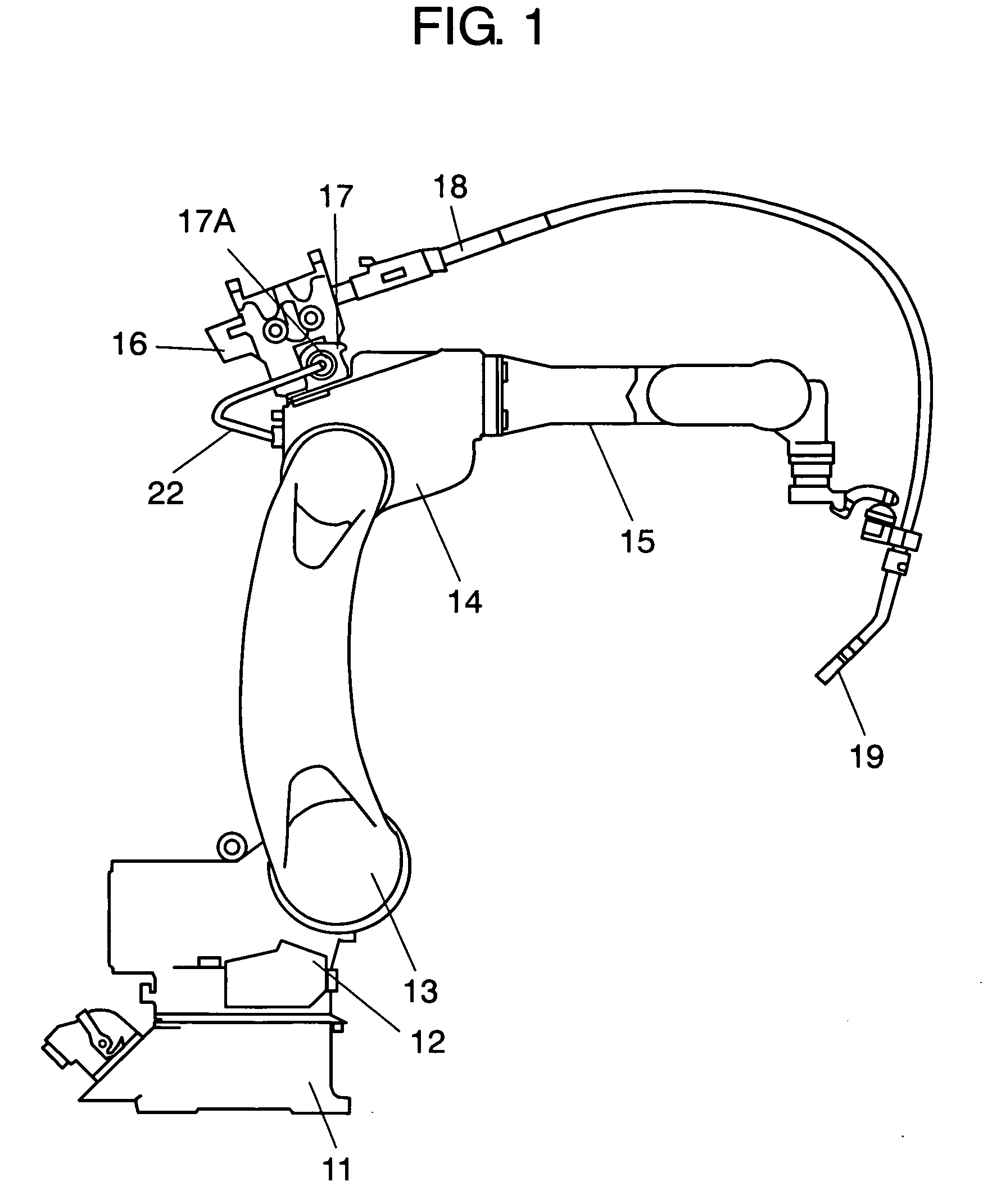
[0018]FIG. 1 is a side view showing an industrial robot in a state in which it is mounted on a floor in accordance with the present exemplary embodiment.

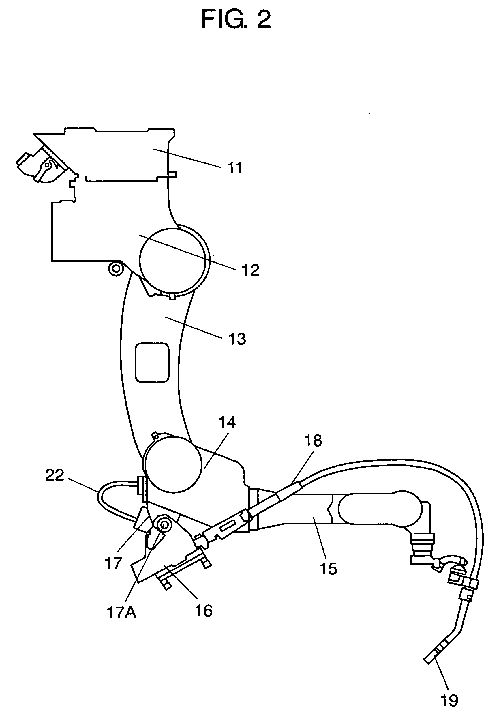
[0019]FIG. 2 is a side view showing the industrial robot in a state in which it is mounted on a ceiling. In the following description, the direction of an industrial robot seen from a floor surface or a ceiling surface is defined as an upper side.

[0020]Base 11 is provided to install the industrial robot on a floor surface, a ceiling surface, or the like. First arm 12 rotates with respect to base 11. Fourth arm 13 pivots with respect to first arm 12, and second arm 14 pivots with respect to fourth arm 13. That is to say, second arm 14 pivots with respect to first arm 12. Third arm 15 pivots with respect to second arm 14. Welding wire feeder (hereinafter, referred to as “feeder”) 16 is provided at the upper side of second arm 14. Torch cable 18 feeds a welding wire from feeder 16 to welding torch 19.

[0021]Fixing device 17 is provided ...


PUM

PropertyMeasurementUnit
electricallyaaaaaaaaaa
rotation angleaaaaaaaaaa
timeaaaaaaaaaa

Abstract

An industrial robot has a base for installation, a first arm, a second arm, a third arm, a wire feeder, a welding torch, and a torch cable. The first arm rotates with respect to the base. The second arm pivots with respect to the first arm. The third arm pivots with respect to the second arm. The torch cable is coupled to the wire feeder and feeds a welding wire to a welding torch. The wire feeder is provided to the second arm and is rotatable around a rotation axis.

Description

[0001]This application is a U.S. national phase application of PCT International Application PCT / JP2006 / 300989.TECHNICAL FIELD[0002]The present invention relates to an industrial robot used for welding, for example, and used in floor-mounted or a ceiling-mounted installation.BACKGROUND ART[0003]Conventionally, as an installing and using method of a welding multi-joint robot (an industrial robot), floor-mounted use, ceiling-mounted use, or the like, is generally known. FIG. 6 is a perspective view showing such an industrial robot when it is used in a state in which it is mounted on a floor. FIG. 7 is a side view showing such an industrial robot when it is used in a state in which it is mounted on a ceiling.[0004]First arm 112 rotates with respect to base 111 for installation. Second arm 113 pivots with respect to first arm 112, and third arm 114 pivots with respect to second arm 113. Furthermore, fourth arm 115 pivots with respect to third arm 114. Welding wire feeder 116 feeds a wel...

Claims


Application Information

Patent Timeline
Patent Type & Authority Applications(United States)
IPC IPC(8): B25J18/04
CPCB23K9/133B23K9/287B25J9/0018Y10T74/20Y10T74/20207Y10T74/20311Y10T74/20305B25J19/0025
Inventor OHARA, TAKAYASUIWAI, SEIJI
Owner KOWA CO LTD
Why Eureka
Try Eureka