Method, Particle Sensor and Particle Sensor System for Measuring Particles

Inactive Publication Date: 2007-11-15
ROBERT BOSCH GMBH
View PDF3 Cites 23 Cited by
  • Summary
  • Abstract
  • Description
  • Claims
  • Application Information

AI Technical Summary

Benefits of technology

[0007] The sensor according to the present Application demonstrates a very compact construction, so that its use is made possible not only in th

Problems solved by technology

Even after the regeneration, soot cannot immediately be accumulated again, for, because of thermal inertia, the sensor requires a certain time for the thermalization of the sensor element by the exhaust gas.
Since,

Method used


Image

  • Method, Particle Sensor and Particle Sensor System for Measuring Particles
  • Method, Particle Sensor and Particle Sensor System for Measuring Particles
  • Method, Particle Sensor and Particle Sensor System for Measuring Particles

Examples


Embodiment Construction

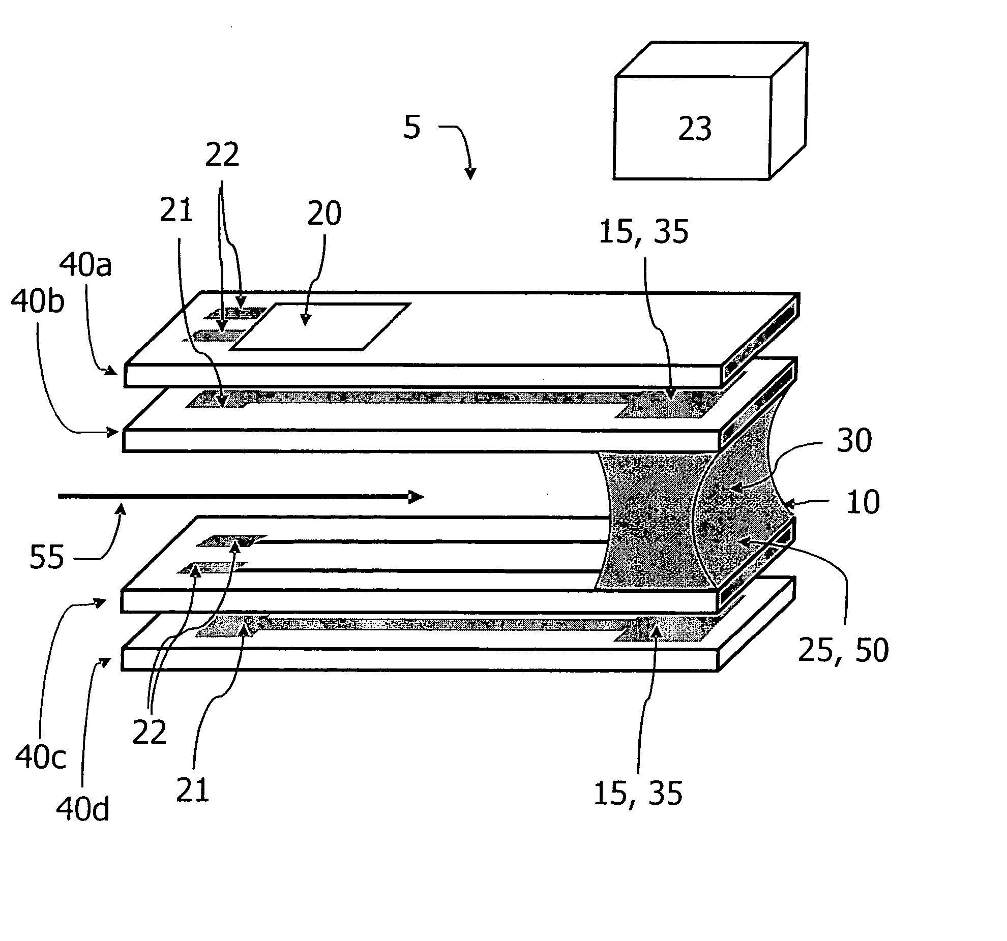
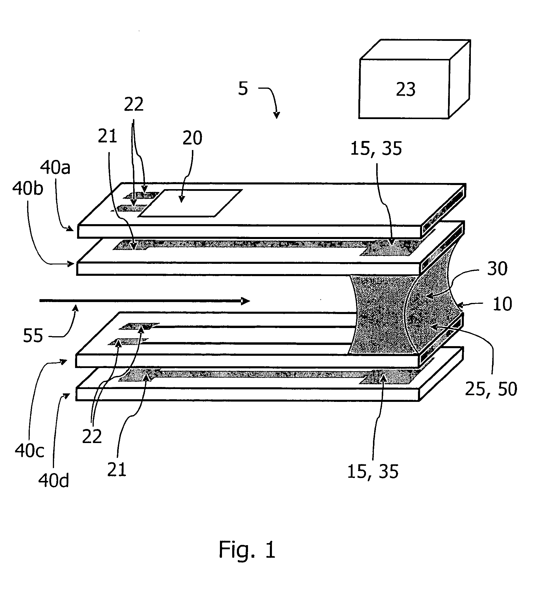
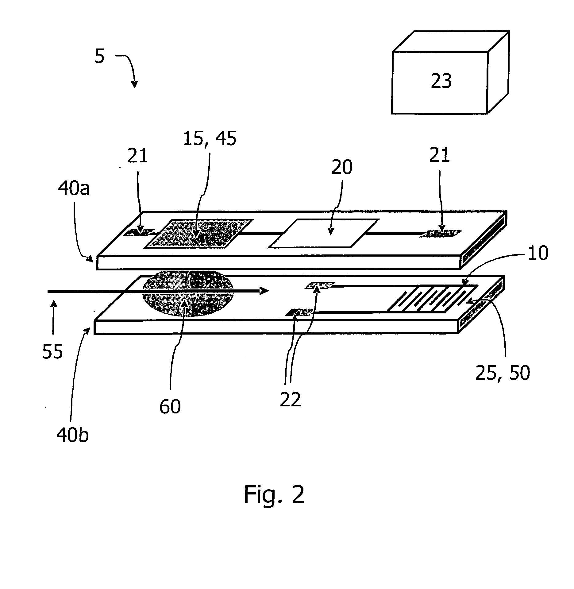
[0011]FIGS. 1 and 2 show a sensor for the detection of particles in a gas stream, which is used for installation in an exhaust branch of a motor vehicle, and may be situated downstream of a soot filter of a motor vehicle having a Diesel internal combustion engine. Alternatively, the sensor may also be situated upstream from the soot filter, in order to determine the soot input into the filter.

[0012] In a first exemplary embodiment as in FIG. 1, particulate sensor 5 has four base elements 40a, 40b, 40c, 40d. Base elements 40a, 40b, 40c, 40d are situated parallel to one another and congruent one above the other, between the two middle ones, 40b, 40c of the four base elements 40a, 40b, 40c, 40d, a greater clearance is provided as compared to the clearance between the two outer ones 40a, 40b and 40c, 40d of the four base elements 40a, 40b, 40c, 40d. Thus, base elements 40a and 40b, as well as 40c and 40d are laminated to each other, whereas between base elements 40b and 40c a gap is pr...


PUM


Abstract

A method and a particle sensor for measuring particles, especially soot particles, in which the particles to be detected accumulate in a measuring region of the particle sensor. The particles located in the gas stream or the particles already accumulated in the measuring region are burned by a combustion device, the combustion being controlled via a control signal from a control unit, which is electrically connected to a measuring device, in such a way that the quantity of the particles adhering in the measuring region remains constant. The physical variable of the combustion device, which leads to the controlled combustion of the particles, is drawn upon as the signal amplitude of the particle sensor.

Description

FIELD OF THE INVENTION [0001] The exemplary embodiment(s) and / or exemplary method(s) of the present invention relates to a method, a particle sensor and a particle sensor system for measuring particles, especially soot particles. BACKGROUND INFORMATION [0002] In order to measure particles, such as soot particles, in the exhaust gas of internal combustion engines, a particle sensor having a device for the detection of soot particles may be mounted in the exhaust pipe. [0003] A sensor is discussed in German patent document no. DE 101 33 384 A1 which is made up of two base (substrate) elements, the base elements having interdigital electrodes and an integrated heater, and being laminated to each other. The interdigital electrodes are used for measuring soot particles, the measurement being based on a resistive measuring principle: An accumulation of particles on the electrode structure leads to a conductivity change or impedance change of the area between the combs of the electrode. Fr...

Claims


Application Information

Patent Timeline
IPC IPC(8): G01N31/12F01N11/00G01N15/06G01N27/04
CPCF01N11/00F01N2560/05Y02T10/47G01N15/0656F01N2560/20Y02T10/40
Inventor SCHMIDT, RALFSCHITTENHELM, HENRIK
Owner ROBERT BOSCH GMBH
Why Eureka
Try Eureka