Drive System for a Cleaning Head Disposed in a Tank

a technology for rotating cleaning heads and tanks, which is applied in the direction of tank cleaning, tank cleaning, hollow article cleaning, etc., can solve the problems of not always operating reliably, its speed cannot be adjusted, and it is difficult to make such a magnetic coupling having permanent magnets work in connection with cleaning heads for tanks

Inactive Publication Date: 2008-11-06
ALFA LAVAL TANK EQUIP
View PDF7 Cites 6 Cited by
  • Summary
  • Abstract
  • Description
  • Claims
  • Application Information

AI Technical Summary

Benefits of technology

[0009]Such a hysteresis coupling provides for an unprecedented possibility of ensuring a quite certain torque transfer of the rotating movement also at the start phase for cleaning heads for tanks. It has been found that in spite of the great difference in the speed of rotation at the moment of start between the driving and the driven magnetic parts, the hysteresis coupling is capable of supplying a torque which is sufficiently great to accelerate the driven magnetic part and t

Problems solved by technology

This may take place by means of various gaskets and stuffing boxes, but it has been found that these do not always operate reliably, in particular after wear, liquid exposure and ageing.
No gear mechanisms are included in the system, and its speed cannot be adjusted.
In practice, however, it is difficult to make such a magnetic coupling having permanent magnets work in connection with cleaning heads for tank

Method used


Image

  • Drive System for a Cleaning Head Disposed in a Tank
  • Drive System for a Cleaning Head Disposed in a Tank
  • Drive System for a Cleaning Head Disposed in a Tank

Examples


Embodiment Construction

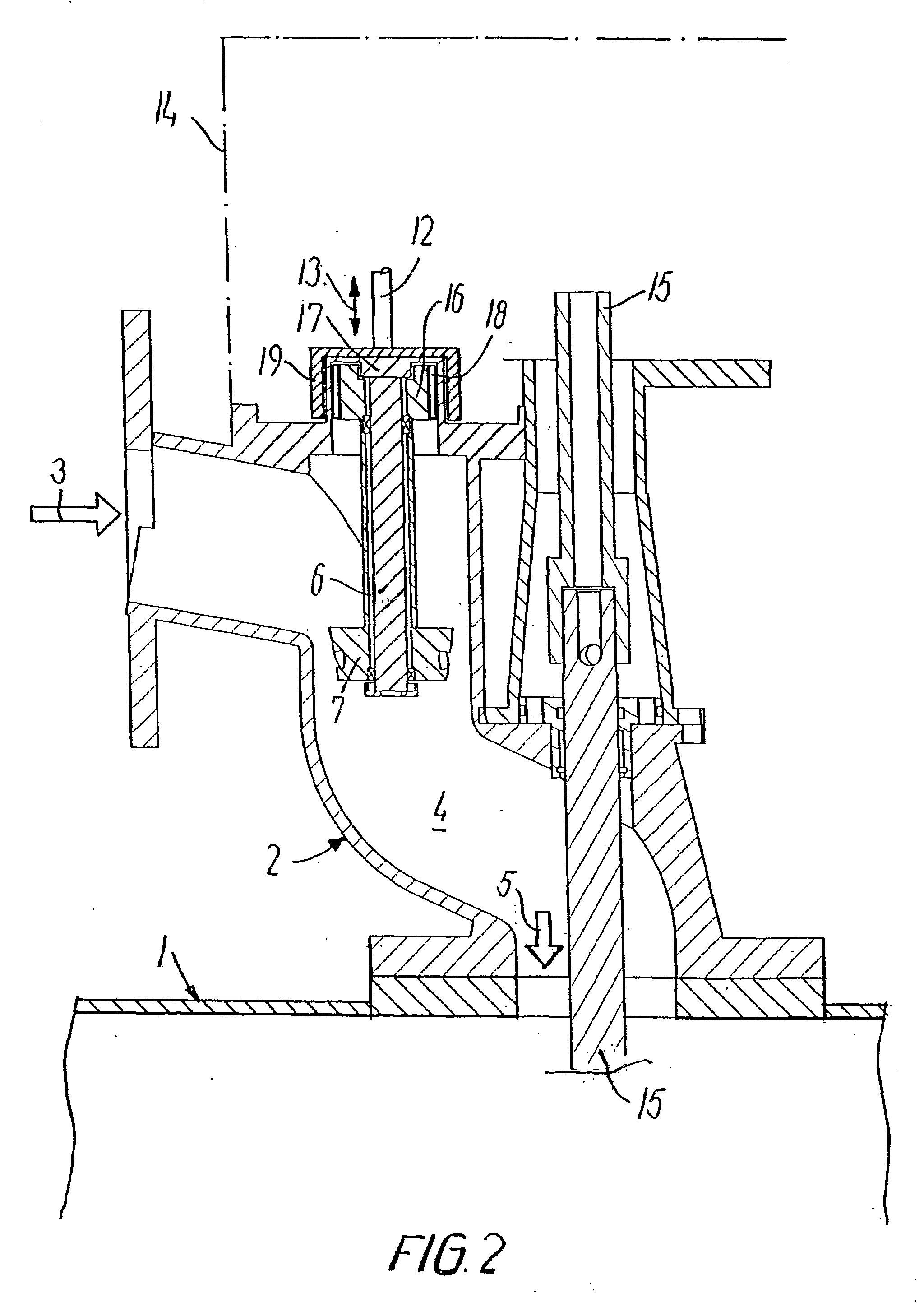
[0019]Three exemplary embodiments shown in FIG. 1, FIG. 2 and FIG. 3, respectively, will be described below.

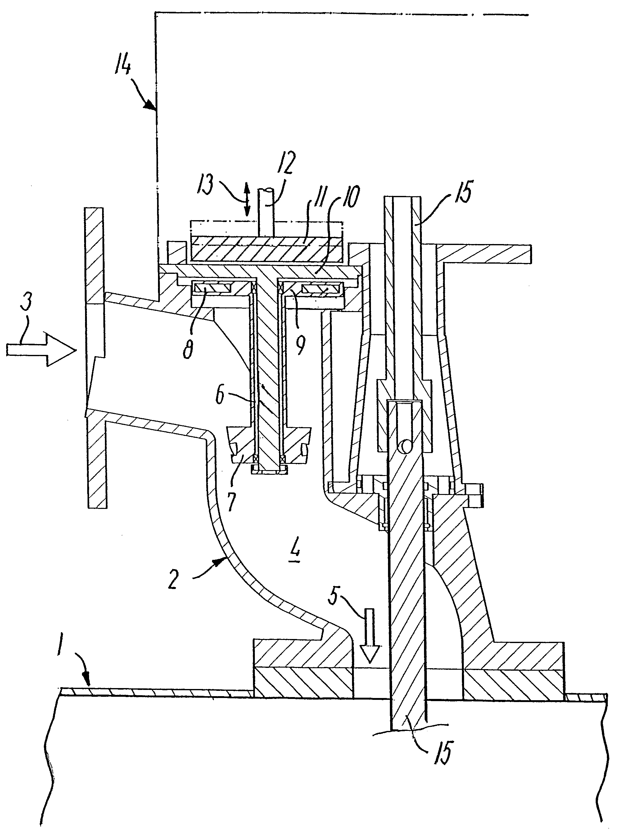
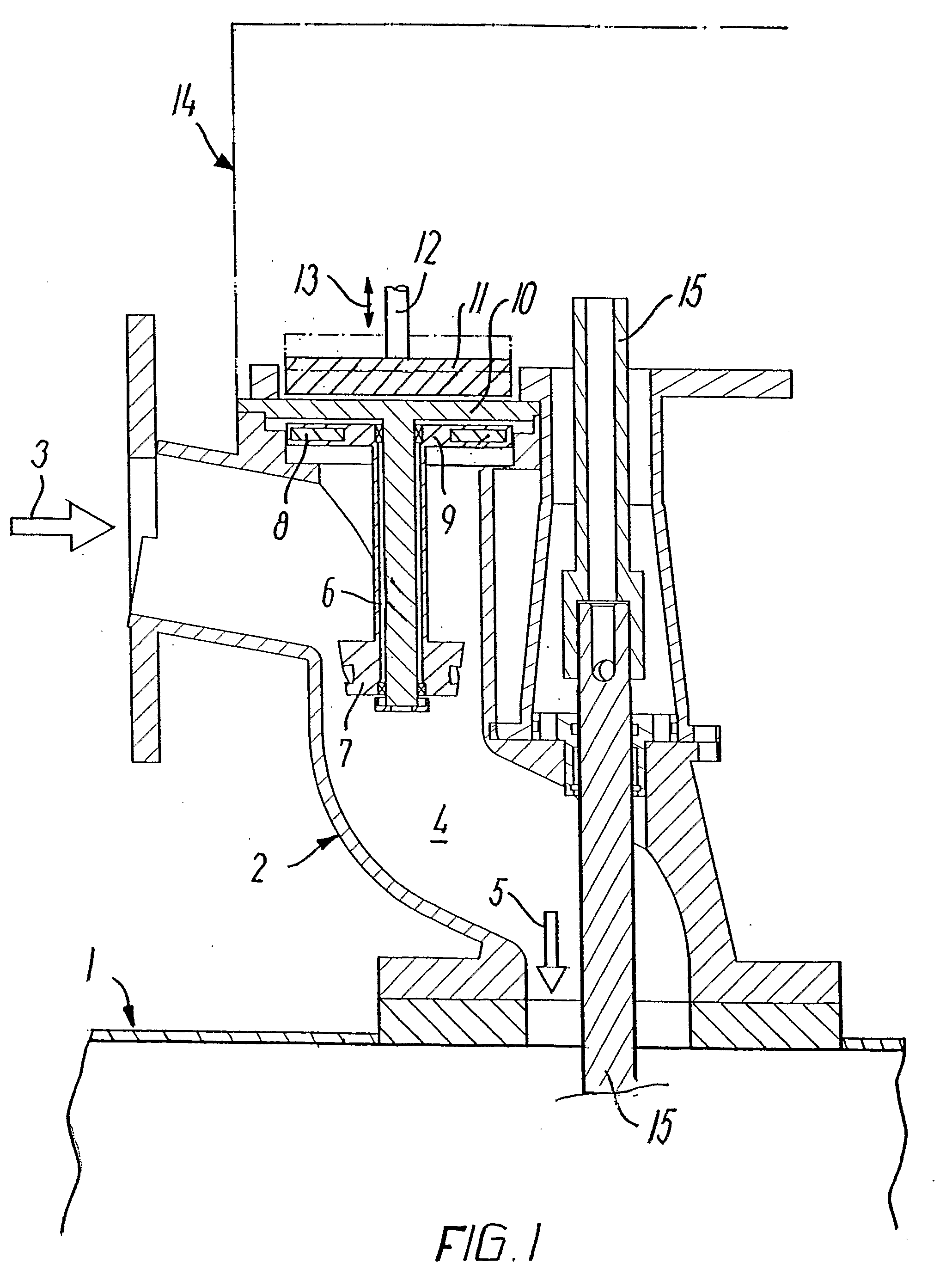
[0020]Apart from the hysteresis coupling itself, a section through the driving part of the cleaning equipment is shown in the examples, viz. a housing 2 which has a liquid inlet 3 for cleaning liquid under pressure, said liquid flowing past a propeller 7 which is thereby caused to rotate with a speed of rotation of several thousand revolutions per minute. The rotation of the propellers 7 is transferred via a shaft 6 to the magnetic part placed in the housing 2. The liquid flow is conveyed through the channel 4 as liquid which is conveyed via a pipe (not shown) to the cleaning head, which is present down in the tank 1.

[0021]The cleaning head is rotatable by means of a rotary shaft 15, and it is also provided with rotating nozzles to eject cleaning liquid under pressure and thereby to clean the entire internal surface of the tank.

[0022]Since the rotation of the cleaning head tak...


PUM


Abstract

When, according to the invention, constructing a drive system for rotating the cleaning head in a tank and allowing the system to comprise a hysteresis coupling having two magnetic parts which are present inside the liquid space (4) and outside this, respectively, a completely liquid-tight separation between the housing (2) and the gear (14) may be ensured. The magnetic part (8, 18) of the hysteresis coupling may be formed by electromagnets, and with a displaceable (13) position of the one part relative to the other part (11, 19) the coupling may be adjusted with respect to the transferred torque and/or speed.

Description

THE PRIOR ART[0001]The invention relates to a drive system for rotating a cleaning head in a tank, said drive system comprising a housing having a propeller mounted in a liquid channel to which cleaning liquid is supplied under pressure, as well as a gear which is driven by the propeller, and which is mounted separated from the cleaning liquid in the housing as a safeguard against leakage of cleaning liquid, said gear transferring the rotation produced by the propeller to a reduced rotation of the cleaning head in the tank, wherein the rotation produced by the propeller is transferred to the gear via a magnetic coupling having coupling parts, the one coupling part of which being disposed inside the housing in the liquid channel and the other coupling part of which being disposed outside the housing, and wherein the coupling parts are configured either as mutually parallel discs or as two cylindrical, concentrically mounted discs.[0002]As a safeguard against leakage it is known to se...

Claims


Application Information

Patent Timeline
IPC IPC(8): B05B3/04H02K49/06B08B9/093B63B57/02
CPCB05B3/0422H02K49/065B63B57/02B08B9/0936B05B3/04B08B9/093H02K49/06
Inventor JORGENSEN, HANS ERIKHJORSLEV, LEON
Owner ALFA LAVAL TANK EQUIP
Why Eureka
Try Eureka