Image Display Device and Image Display Method
a display device and image technology, applied in static indicating devices, non-linear optics, instruments, etc., can solve the problems of reducing the display performance, difficult to display each color by 8 bits, and narrowing the divided voltage range, so as to improve the viewing angle characteristic
- Summary
- Abstract
- Description
- Claims
- Application Information
AI Technical Summary
Benefits of technology
Problems solved by technology
Method used
Image


Examples
first embodiment
[0099]First, an image display device 10 will be explained
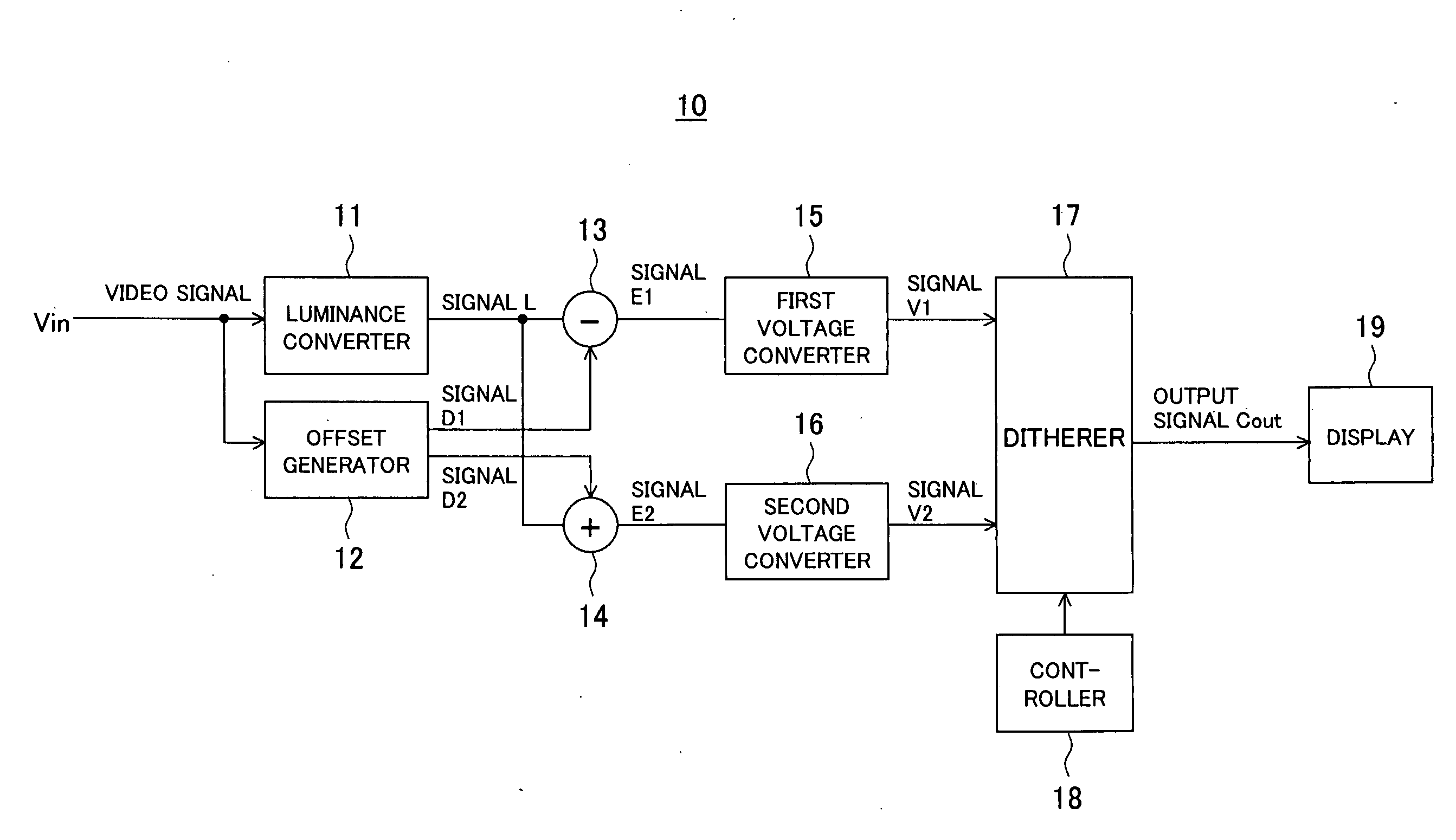
[0100]FIG. 3 is a diagram showing an example of the configuration of an image display device according to a first embodiment of the present invention.
[0101]The image display device 10 is provided with, as shown in FIG. 1, a luminance converter 11 for converting a video signal H given as an applied signal voltage to a luminance signal based on a predetermined nonlinear characteristic, an offset generator 12 supplied with the input video signal H, a first adder circuit 13 and a second adder circuit 14 for adding and subtracting output signals from the luminance converter 11 and an offset table, a first voltage converter 15 supplied with a computation result of the first adder circuit 13, a second voltage converter 16 supplied with a computation result of the second adder circuit 14, a ditherer 17 supplied with signals V1 and V2 output from the first and second voltage converters 15 and 16, a controller 18 for controlling the di...
second embodiment
[0164]Next, an image processing apparatus 20 expressing a middle gray-scale of an input video signal by a field train comprised of a plurality of fields so as to improve the viewing angle characteristic will be explained.
[0165]The image display device 10 of the first embodiment used the technique of dithering in the spatial direction to express one gray-scale by a plurality of pixels so as to improve the viewing angle characteristic.
[0166]As opposed to this, the image display device 20 of the second embodiment expresses one gray-scale by pixels of a plurality of screens arranged in the time direction to improve the viewing angle characteristic.
[0167]Below, one screen will be also referred to as a “field” and a train comprised of a plurality of fields will be referred to as a “field train”. Note that the term “field” in the present description is not limited to the field in so-called interlaced scan.
[0168]FIG. 9 is a block diagram showing an example of the configuration of the image...
fourth embodiment
[0305]Further, in the present embodiment, as shown in FIG. 24C, in comparison with the second method, in the γ characteristic at the viewing angle of 60 degrees, the actual characteristic shown by B tends to give a waveform further approximating the ideal curve shown by A.
[0306]Accordingly, even when the fourth method is employed, there is the advantage that improvement of the viewing angle characteristic of the middle gray-scale is possible.
[0307]FIG. 25A shows the transmittance characteristic with respect to the input gray-scale of a liquid crystal display device corresponding to the general spatial sub pixel processing, and FIG. 25B shows the transmittance characteristic with respect to the input gray-scale of a liquid crystal display device employing the fifth method combining the second method of the present embodiment and spatial sub pixel processing.
[0308]As previously explained, in a general liquid crystal display device, as shown in FIG. 25A, in the γ characteristic at the ...
PUM
 Abstract
Description
Claims
Application Information