Vertical bubble machine

a vertical and bubble machine technology, applied in toys, entertainment, etc., can solve the problems of contaminating the surface area, wasting a significant amount of bubble fluid, and generally undesirable to blow bubbles in the horizontal direction

Inactive Publication Date: 2008-11-06
WING HING MFG
View PDF10 Cites 13 Cited by
  • Summary
  • Abstract
  • Description
  • Claims
  • Application Information

AI Technical Summary

Problems solved by technology

However, it is generally undesirable to blow bubbles in the horizontal direction for several reasons.
For example, the bubble generating machine is often placed on a horizontal surface during use, but blowing bubbles in a horizontal direction causes a significant numbers of bubbles to burst on the horizontal surface, thus wasting a significant amount of bubble fluid.
The burst bubbles also contaminate the surface area surrounding the bubble generating machine as well as the machine itself, necessitating subsequent cleaning of these surfaces.
Blowing bubbles in a vertical direction is generally not possible with these systems, as the bubble heads must be rotated through a horizontal reservoir of bubble solution and consequently must be orthogonal, or at a right angle, to such bubble solution.
This makes the conventional machine 100 less efficient at producing bubbles.

Method used


Image

  • Vertical bubble machine
  • Vertical bubble machine
  • Vertical bubble machine

Examples


Embodiment Construction

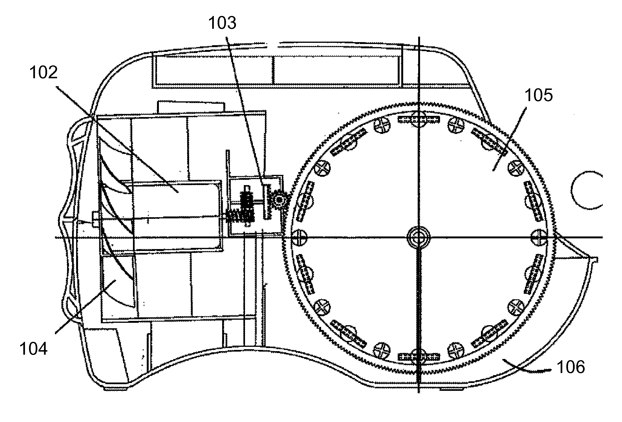
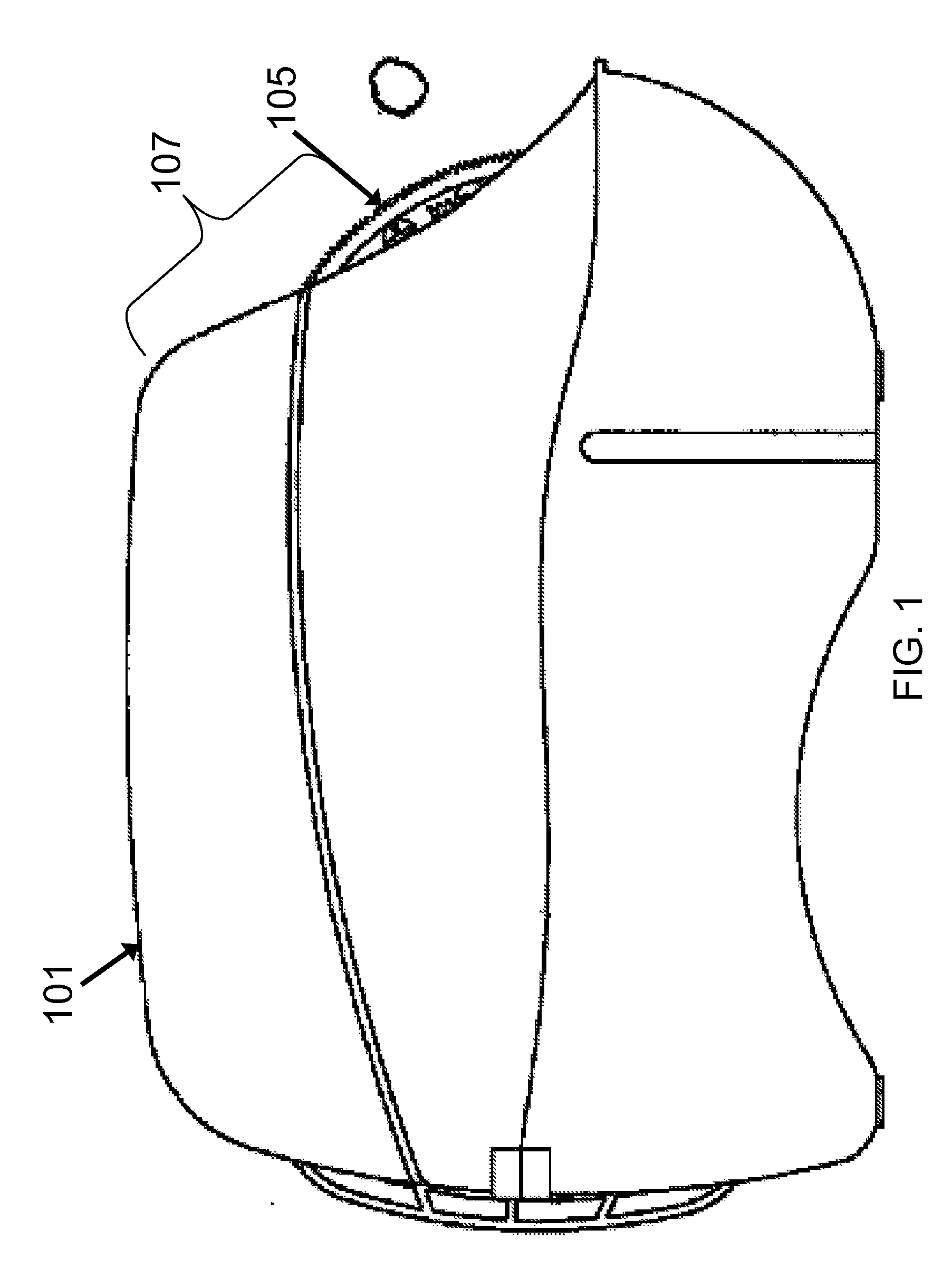
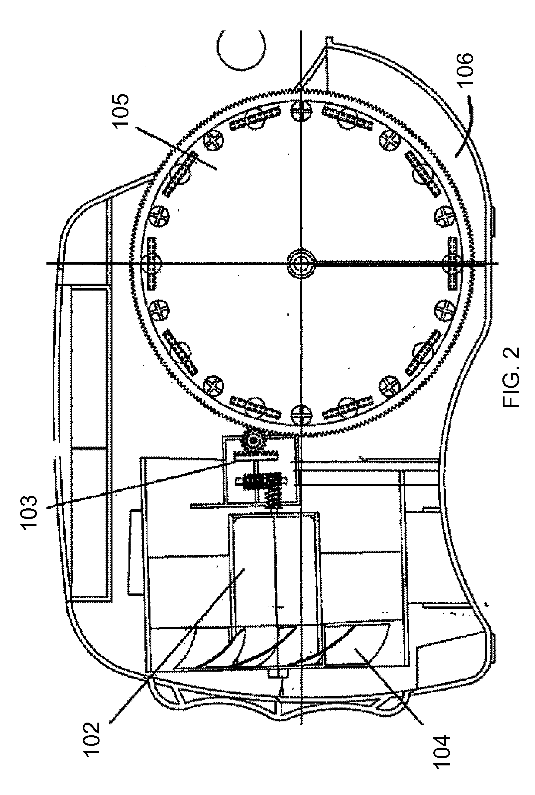
[0011]The present invention reverses the configuration of the motor and fan and turns the bubble wheel at right angles to significantly reduce the size of the bubble machine. In the prior art machine above, the configuration is fan>motor>wheel, and the plane of the bubble wheel is in-line with the axis or plane of the fan and motor. By putting the wheel at right angles, and / or by reversing the motor and fan configuration (motor>fan>wheel), and / or by sitting the fan wholly or partially inside the wheel, the current invention significantly reduces the footprint of the device.

[0012]According to one aspect of the present invention, a compact size bubble generating machine is provided, that comprises a housing having an upper opening; a bubble generator positioned inside the housing and adjacent to the upper opening; an impeller positioned inside the housing; and a motor positioned inside the housing and operatively coupled to the impeller and the bubble generator. In this variation, the...


PUM


Abstract

The current invention discloses a compact size bubble generating machine. According to one aspect of the present invention, there is provided a bubble generating machine comprising a housing having a top opening; a bubble generator positioned inside the housing and adjacent to the top opening; an impeller positioned inside the housing; and a motor positioned inside the housing and operatively coupled to the impeller and the bubble generator, wherein the motor, when actuated, causing the impeller and the bubble generator to rotate simultaneously.

Description

PRIOR RELATED APPLICATIONS[0001]Not applicable.FEDERALLY SPONSORED RESEARCH STATEMENT[0002]Not applicable.REFERENCE TO MICROFICHE APPENDIX[0003]Not applicable.FIELD OF THE INVENTION[0004]The present invention relates to bubble generating toys, and in particular, to a compact size bubble generating machine that generates continuous streams of bubbles in desired directions.BACKGROUND OF THE INVENTION[0005]Bubble generating machines have many adaptations and uses and are particularly appealing to young children. Many bubble generating machines are already available on the market. For example, FIGS. 1-3 shows a conventional bubble generating machine 100. Specifically, FIG. 1 is a side view, FIG. 2 is a side sectional view, and FIG. 3 is a top sectional view of the same conventional bubble machine.[0006]This bubble generating machine 100 mainly comprises an outer cover or shell 101, a motor 102, a gear box 103, an impeller 104, a wheel 105, and a bubble solution reservoir 106. The shell ...

Claims


Application Information

Patent Timeline
Patent Type & Authority Applications(United States)
IPC IPC(8): A63H33/28
CPCA63H33/28
Inventor LO, WAI CHUNGLEUNG, YIN PAK
Owner WING HING MFG
Why Eureka
Try Eureka