Autonomous Ventilation System

a technology of ventilation system and automatic control, which is applied in ventilation system, heating type, stove or range, etc., can solve the problems of needlessly wasting energy not only in the operation of ventilation system, and achieve the effect of reducing or eliminating at least some of the disadvantages and problems

Inactive Publication Date: 2008-11-06
HALTON GROUP LTD
View PDF10 Cites 29 Cited by
  • Summary
  • Abstract
  • Description
  • Claims
  • Application Information

AI Technical Summary

Benefits of technology

[0006]The present disclosure provides an autonomous ventilation system that substantially eliminates or reduces at least some of the disadvantages and problems associated with previous methods and systems.
[0008]Technical advantages of certain embodiments may include a reduction in energy consumption, an increase in the comfort of the ventilated area, a decrease in noise, and an increase in the lifespan of environmental sensors and fans. Embodiments may eliminate certain inefficiencies such as needlessly ventilating valuable air from an area that was supplied by a heating, ventilation, and air conditioning (“HVAC”) system.

Problems solved by technology

This needlessly wastes energy not only associated with the operation of the ventilation system, but also due to the ventilation of uncontaminated air supplied to the kitchen by a heating and cooling system.

Method used


Image

  • Autonomous Ventilation System
  • Autonomous Ventilation System
  • Autonomous Ventilation System

Examples


Embodiment Construction

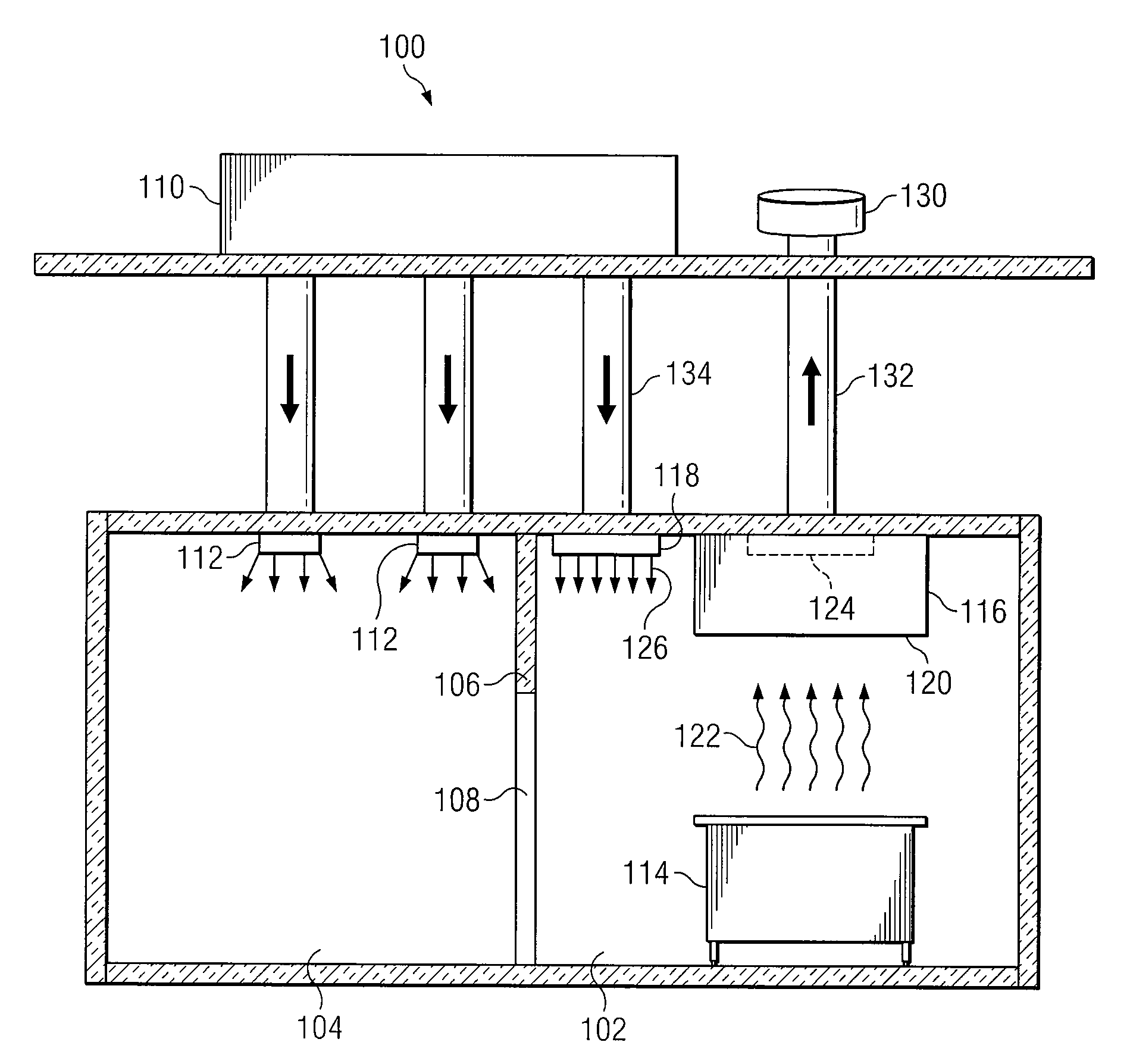
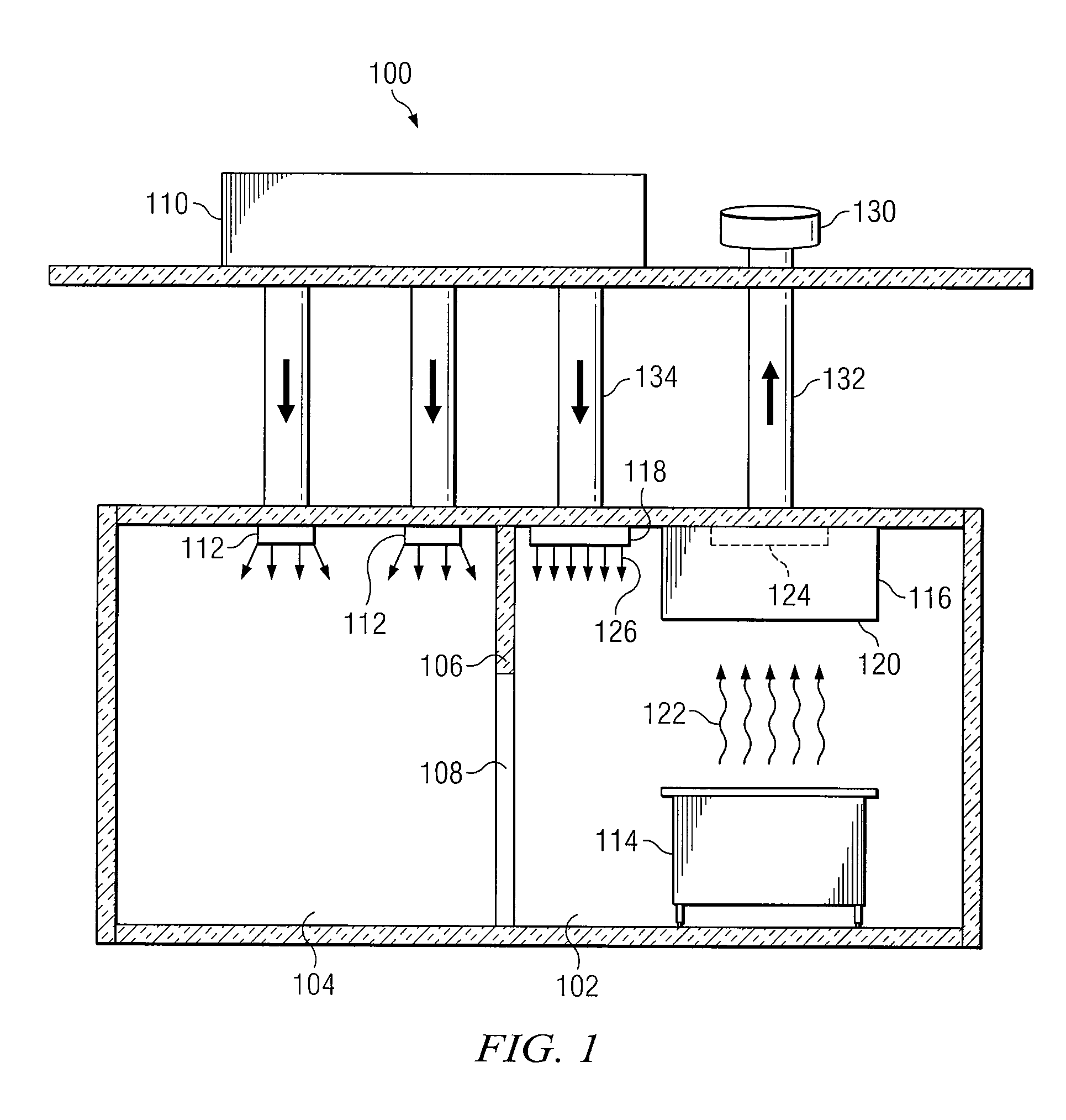
[0015]FIG. 1 depicts a facility 100 where a particular embodiment may be utilized. Facility 100 may be a restaurant, for example, that includes a kitchen 102 and at least one adjacent room 104 separated by a wall 106. Wall 106 contains a doorway 108 that allows access between kitchen 102 and adjacent room 104. Facility 100 also includes an HVAC system 110 that provides conditioned air to the interior of facility 100 via interior vents 112. Kitchen 102 includes one or more pieces of cooking equipment 114, an exhaust hood 116, a ceiling supply air vent 118, and a ceiling exhaust vent 124. Examples of cooking equipment 114 include, but are not limited to, stoves, cooktops, ovens, fryers, and broilers. Exhaust hood 116 is oriented such that a downward-facing opening 120 is operable to direct an air contaminant 122 associated with the operation of cooking equipment 114 through ceiling exhaust vent 124 and ultimately out an exterior exhaust vent 130 via an exhaust duct 132. Air contaminan...


PUM


Abstract

An autonomous ventilation system includes a variable-speed exhaust fan, a controller, an exhaust hood, and a spillage sensor. The exhaust fan removes air contaminants from an area. The controller is coupled to the exhaust fan and adjusts the speed of the exhaust fan. The exhaust hood is coupled to the exhaust fan and directs air contaminants to the exhaust fan. The spillage sensor is coupled to the controller, detects changes in an environmental parameter in a spillage zone adjacent to the exhaust hood, and communicates information relating to detected changes in the environmental parameter to the controller. The controller adjusts the speed of the exhaust fan in response to information relating to detected changes in the environmental parameter.

Description

CROSS REFERENCE TO RELATED APPLICATIONS[0001]This application claims the benefit under 35 U.S.C. §119(e) of U.S. Provisional Application No. 60 / 915,974 filed May 4, 2007 entitled “Smart Kitchen Ventilation Hood.”TECHNICAL FIELD[0002]This disclosure relates in general to control systems and more particularly to an autonomous ventilation system.BACKGROUND[0003]Ventilation systems are commonly found in modern residential, restaurant, and commercial kitchens. Heat, smoke, and fumes are an ordinary byproduct of cooking many foods and must be removed in order to protect the health and comfort of those present in the kitchen and adjacent areas. Ventilation systems provide an effective way to capture excessive heat, smoke, and fumes generated in kitchens and ventilate them to the atmosphere where they pose no threat to health or safety.[0004]A typical ventilation system consists of an exhaust hood positioned over pieces of cooking equipment that are known to produce heat, smoke, or fumes. T...

Claims


Application Information

Patent Timeline
Patent Type & Authority Applications(United States)
IPC IPC(8): F24C15/20
CPCF24C15/2021F24F11/0012F24C15/20F24F11/30F24F2110/10F24F11/77F24F11/76F24F11/46F24F11/63F24C15/2042
Inventor BURDETT, MICHAEL P.REICH, DANIEL
Owner HALTON GROUP LTD
Why Eureka
Try Eureka