
Method and apparatus for automatic generation of information system user interfaces

a technology of information system and user interface, applied in the field of user interface and software engineering, can solve the problems of long delay, insufficient domain model consideration of ui specification methods, and bugs in business logic code itsel

Inactive Publication Date: 2008-11-06
SOSY
View PDF36 Cites 82 Cited by
  • Summary
  • Abstract
  • Description
  • Claims
  • Application Information

AI Technical Summary

Benefits of technology

[0020](1) The software production system contains a unique specification model to facilitate modeling both functional and user interface thereby enabling the production of a single model which fully specifies both the business logic and the user interface (as well as other things) thereby eliminating the synchronization problem between functional and user interfaces requirements that existed in the prior art.
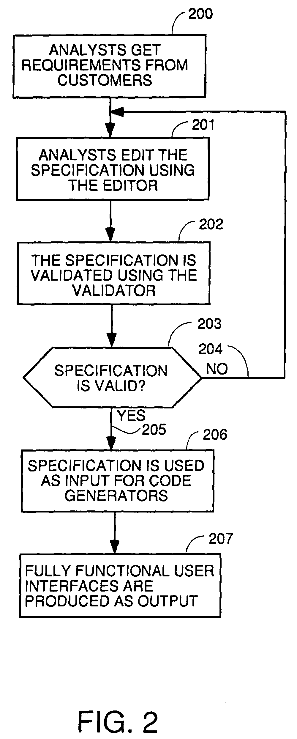
[0025]Interaction Units (IUs) are of various types and represent templates that define particular styles of user interface display and operation. Each Interaction Unit is a template of an object in the object oriented programming sense (hereafter just referred to as objects). Each object will have a data structure which contains data which defines the state of the object and methods or function calls or algorithms that control a computer to operate on the data structure to change the state of the object. Every object has a messaging mechanism to communicate with other objects. The editor contains executable code which implement objects with services or functions to create, edit and destroy the patterns in the meta-model such as IU to allow an analyst to build a User Interface Model which completely defines the desired user interface. The patterns such as IU specified in the User Interface Model are converted by the editor into a data structure defined in Section C hereof which embodies a specification in a formal language of the desired user interface. This formal specification is then validated against the predetermined validation rules based upon the semantics and syntax of the formal language being used. This process points out any fatal errors and gives warning messages regarding non fatal errors. Corrections can then be made with the editor. After validation, the formal language specification is then automatically translated into working, bug-free code. This process happens about much faster than hand writing of code to implement a user interface because of the elimination of large amounts of debugging time.
[0031]The method described and implemented by the apparatus allows the analyst to develop business software faster that third party tools and methods.

Problems solved by technology

UI specification methods do not consider enough the domain model (the functionality of the application).
Coding the business logic separately may lead to bugs in integration with the UI and bugs in the business logic code itself.
This lengthens the delay from conception to first sales in the market (time to market) because of possibility long delays in debugging the business logic code.
Furthermore, this prior art UI specification tools do not have: a precise, unambiguous semantics which can be validated to eliminate bugs in the IU code, that can generate IU code automatically from the validated specification of the user interface and able to connect with a generated business logic component and persistence layer also generated to conform an entirely automatic generated application.
On the other hand, methods and notations for the specification of functional requirements of computer programs (tools to define models of the business logic of a program) such as OMT or UML do not consider user interface requirements as well.
This produces synchronization problems whenever one of the specification changes.
In other words, when one of the specifications changes, the other specification “breaks” and code written implementing this other specification will no longer work with the code written implementing the first specification.
This requires expensive and time consuming reworking of the second specification.
Such code cannot be compiled directly and needs hand coding before a program which can run as a final application exists.
Previous UI modeling tools do not present a set of primitives that can be invoked to specify the elements of a user interface for business applications.
However, these prior art tools propose very low level primitives that can not be used in medium-sized industrial projects without suffering scalability problems.
Wisdom or CTT has resulted in tools which have not been tested in industrial projects and has not been fine-tuned for such scalability requirements.
As a result, this makes it impossible to generate validated specifications of the user interface model and bug-free code from an imprecise specification.

Method used


Image

  • Method and apparatus for automatic generation of information system user interfaces
  • Method and apparatus for automatic generation of information system user interfaces
  • Method and apparatus for automatic generation of information system user interfaces

Examples


Embodiment Construction

[0061]The invention improves an automatic software production system as described in a United States patent application entitled Automatic Software Production System, filed Apr. 4, 2000, Ser. No. 09 / 543,085 and three continuation-in-part of the same title all filed on Jun. 1, 2001, and having Ser. Nos. 09 / 872,413, 09 / 872,087, and 09 / 872,333, respectively, all of witch describe systems to automatically produce robust and fully functional business applications from specifications and all of which are hereby incorporated by reference.

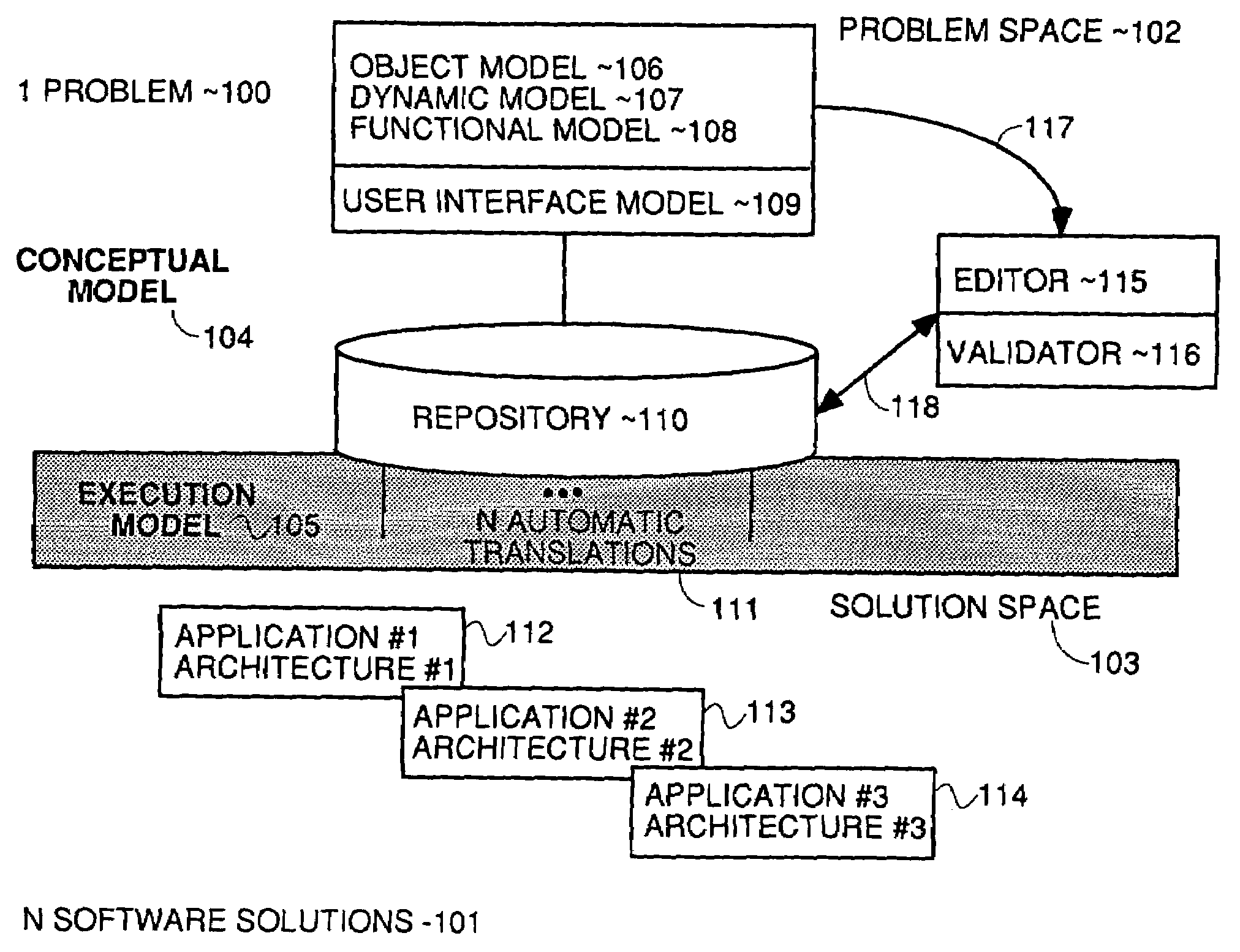
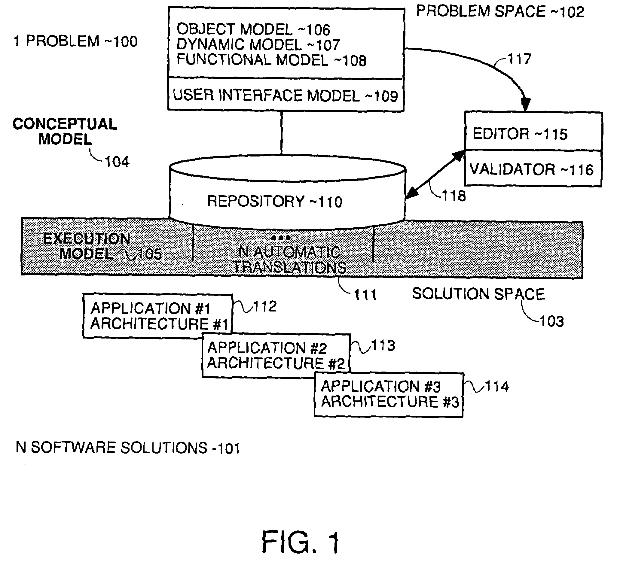
[0062]Referring to FIG. 1 there is shown a block diagram describing an overview of the software development process. A given problem 100 can be implemented in many ways 101 taking different analysis, design and implementation decisions. The abstraction separation between the analysis and the implementation is called Problem Space 102 and Solution Space 103, respectively. In this scenario, the Conceptual Model 104 is a set of graphical objects defining the ...


PUM


Abstract

A method and apparatus for the specification and automatic generation of user interfaces of information system (computer programs) is provided. The method is based in pattern language to specify requirements in an un-ambiguous mode and with precise semantics. The pattern language allows a user interface model to be composed using elements of the pattern language (computer objects in the object oriented programming style) which fully specify the desired user interface. The semantics of the objects in the user interface model have one and only one definition such that user interface model can be validated in a validation process. The validation process eliminates bugs in the final computer program code which is automatically produced from the user interface model. A model (meta-model), an editor tool (computer program) implementing the model for creating specifications of the user interface model, DTD specification, code generators, and other artifacts are depicted and described here for obtaining such user interfaces for different platforms (computers and operating systems) and different programming languages without manual coding of the computer code to implement the user interface. The software obtained is ready to run and it is able to communicate with a business server component using a standardized Application Programmatic Interface (API).

Description

CROSS REFERENCE TO RELATED APPLICATIONS[0001]This is a continuation-in-part of a prior U.S. patent application entitled Automatic Software Production System, Ser. No. 09 / 872,413, filed Jun. 1, 2001, which was a continuation-in-part of prior U.S. patent application of the same title, Ser. No. 09 / 543,085, filed Apr. 4, 2000 which are hereby incorporated by reference. Two other CIPS of Ser. No. 09 / 543,085, filed Apr. 4, 2000 exist having Ser. Nos. 09 / 872,087 and 09 / 872,333, both filed Jun. 1, 2001.REFERENCES[0002]Pedro J. Molina, Oscar Pastor, Sofia Marti, Juan J. Fons and, Emilio Insfrán. “Specifying Conceptual Interface Patterns in an Object-Oriented Method with Code Generation” In Proceedings of 2nd IEEE Workshop on User Interfaces for Data Intensive Systems UIDIS'01. IEEE Computer Society, IEEE Press, ISBN 0-7695-0834-0, pages 72-79, May 2001.[0003]Pedro J. Molina, Santiago Meliá and Oscar Pastor, “Just-UI: A User Interface Specification Model”, Computer-Aided Design of User Interf...

Claims


Application Information

Patent Timeline
Patent Type & Authority Applications(United States)
IPC IPC(8): G06F17/30G06F9/44G06F9/46G09G5/00
CPCG06F8/35G06F8/38G06F17/30371G06F16/2365
Inventor MOLINA-MORENO, PEDRO JUANPASTOR-LOPEZ, OSCARMOLINA-UDAETA, JUAN CARLOSBARBERA-ALONSO, JOSE MIGUEL
Owner SOSY
Learn More