
Method of projecting zero-convergence aiming beam on a target and zero-convergence laser aiming system

Inactive Publication Date: 2008-11-13
RASCHELLA MICHAEL +1
View PDF20 Cites 33 Cited by
  • Summary
  • Abstract
  • Description
  • Claims
  • Application Information

AI Technical Summary

Benefits of technology

[0017]Accordingly, an object of the present invention is to provide an improved method of projecting a zero-convergence aiming beam on a target and a zero-convergence laser aiming system that obviates the above-mentioned disadvantages.
[0019]Next object of the present invention is to present a method of projecting a zero-convergence aiming beam on a target and a zero-convergence laser aiming system which is easily pre-calibrated one time and out of dangerous zones or prior to usage.
[0020]Another object of the present invention is to provide a method of projecting a zero-convergence aiming beam on a target and a zero-convergence laser aiming system which does not require adjustment in the dangerous zone or during use.
[0023]A further object of the present invention is to provide a method of projecting a zero-convergence aiming beam on a target and a zero-convergence laser aiming system, which is compact in design.
[0024]Still another object of the present invention is to provide a method of projecting a zero-convergence aiming beam on a target and a zero-convergence laser aiming system, which is lightweight.
[0027]According to a first embodiment of the present invention, it is describing a method of projecting a zero-convergence aiming beam on a target by a zero-convergence laser aiming system having at least two laser modules. The laser modules are adjustably fixed to a tube and aligned with the axis line of said tube. The method comprises the steps of sending a first linear beam from a first laser module on the target; sending a second linear beam from a second laser module on the target. The first and second linear beams being mutually oriented in a non-parallel manner to create on the target the aiming beam projection as an “X” intersection to ensure accurate and convenient shooting, aiming or aligning regardless of the distance to the target and the skill or experience of an operator.

Problems solved by technology

While the use of now existing disrupters is effective in neutralizing a target package, the aiming operation of the disrupter is not without problems.
In many instances the disrupter should be moved closer or further from the potentially explosive package and it is difficult to aim the barrel in a quick and exact manner at a given distance.
Even as some of the above mentioned systems are practical, all of them suffer from the same principle defect related to a distance change, in that they need to be additionally calibrated during the disrupter's preparation at the scene.
This is especially problematic when using a robotic platform since the distance that the robotic platform will be from the target when it arrives at the said target cannot be easily predicted from the operator's point of view.
This specified defect makes them unusable for quick secured operations.

Method used


Image

  • Method of projecting zero-convergence aiming beam on a target and zero-convergence laser aiming system
  • Method of projecting zero-convergence aiming beam on a target and zero-convergence laser aiming system
  • Method of projecting zero-convergence aiming beam on a target and zero-convergence laser aiming system

Examples


first embodiment

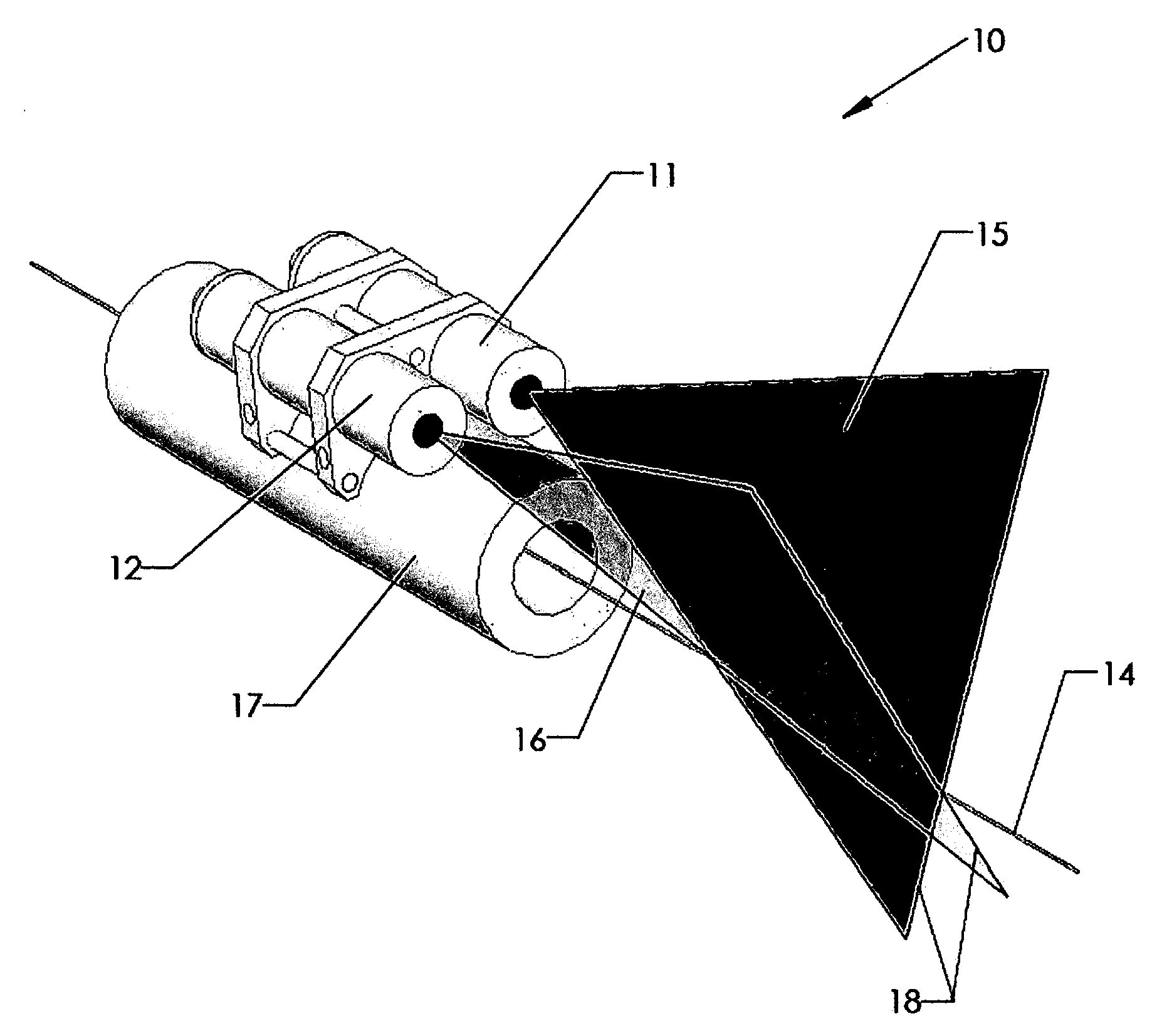
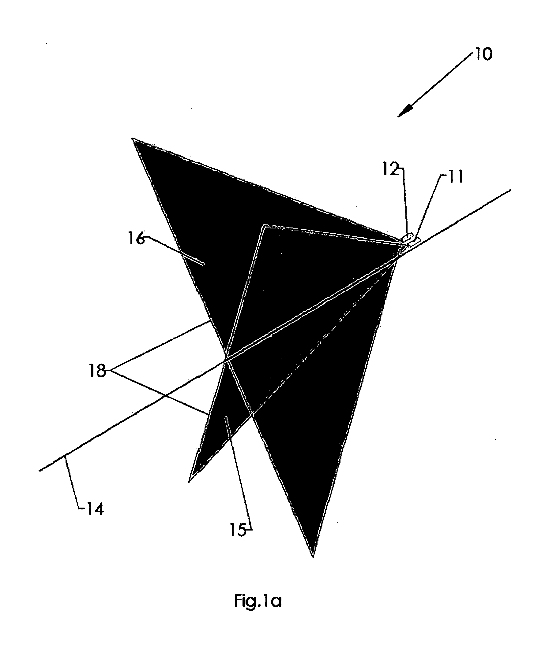
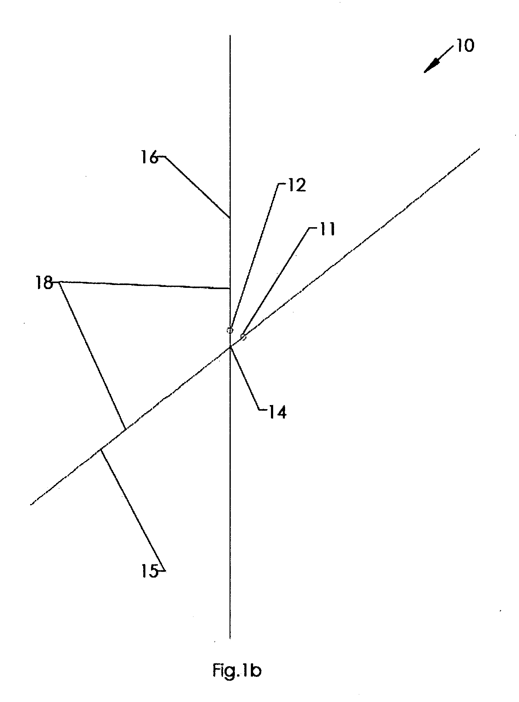
[0046]Referring to FIGS. 1a and 1b, the method comprises the steps of sending a first linear beam 15 from a first laser module 11 on the target, object, etc. . . . ; sending a second linear beam 16 from a second laser module 12 on the target, object, etc. . . . The first 15 and second 16 linear beams are mutually oriented in a non-parallel manner. It allows to create on the target, object, etc. . . . the aiming beam projection 18 as an “X” intersection ensuring accurate and convenient shooting, aiming or aligning regardless of the distance to the target, object, etc. . . . and the skill or experience of an operator.

[0047]Referring to FIGS. 2a, 2b, 2c, 2d, 3 and 4, a second embodiment 10a of the method comprises the steps of sending a first linear beam 15 from a first laser module 11 on the target, object, etc. . . . ; sending a second linear beam 16 from a second laser module 12 on the target, object, etc. . . . The first 15 and second 16 linear beams are mutually oriented in a righ...

second embodiment

[0049]The zero-convergence laser aiming system 10a of the second embodiment is adjustably fixed, attached, etc. . . . to a tube 17 and aligned with the axis line 14 of said tube. The system 10a comprises a first laser module 11 sending a first linear beam 15 on the target, object, etc. . . . ; a second laser module 12 sending a second linear beam 16 on the target, object, etc. . . . The first 15 and second 16 linear beams are mutually oriented in a right angled manner to create on the target, object, etc. . . . the aiming beam projection as a cross-hair 18a to ensure accurate and convenient shooting, aiming or aligning regardless of the distance to the target, object, etc. . . . and the skill or experience of an operator.

[0050]The zero-convergence laser aiming system 10 or 10a would be easily adjusted for user specific needs. Our laser aiming system 10 or 10a does need to be calibrated once attached to the tube 17. Even if the laser aiming system 10 or 10a is removed and then reatta...


PUM


Abstract

A method of projecting a zero-convergence aiming beam on a target and a zero-convergence laser aiming system are disclosed. The method comprises steps of sending a first linear beam from a first laser module on the target; sending a second linear beam from a second laser module on the target, the first and second linear beams being mutually oriented in a non-parallel manner to create on the target the aiming beam projection as an “X” intersection to ensure accurate and convenient shooting regardless of the distance to the target and the skill or experience of an operator. The laser aiming system is adjustably fixed to a tube and aligned with an axis line of said tube, and comprises a first laser module sending a first linear beam on the target; a second laser module sending a second linear beam on the target, the first and second linear beams being mutually oriented in a non-parallel manner.

Description

FIELD OF THE INVENTION[0001]The present invention relates to aiming systems and more particularly to method of projecting a zero-convergence aiming beam on a target and a zero-convergence laser aiming system. The invention is mainly applicable to the field of disrupters but not limited to, for the explosive ordnance disposal industry in which the laser aiming systems are used to create one or more aiming beams. It may also be used as a range finder with the proper visual aids.BACKGROUND OF THE INVENTION[0002]In the prior art, disrupters are used in various forms to neutralize a potentially explosive package so that the package does not detonate in its intended and harmful way. High speed water jets or other projectiles have been used to break apart the package.[0003]The water acts in a way as to knock out the fuse, powers supply, etc. before the potential explosive can initiate and create a damaging impact.[0004]In certain instances, a human, robot or unmanned device positions the d...

Claims


Application Information

Patent Timeline
IPC IPC(8): F41G1/00G01C15/00
CPCF41G1/35G01C15/004
Inventor RASCHELLA, MICHAELTANASE, MARIN
Owner RASCHELLA MICHAEL
Features
  • Generate Ideas
  • Intellectual Property
  • Life Sciences
  • Materials
  • Tech Scout
  • Unparalleled Data Quality
  • Higher Quality Content
  • 60% Fewer Hallucinations
Learn More