Automatic central buffer coupling

a central buffer and coupling technology, applied in the direction of buffer cars, railway coupling accessories, draw-gear, etc., can solve the problems of damage or even destruction of the interface the normal regeneratively-configured draw-gear and conceivably the coupling link between the individual car bodies, etc., to achieve optimal crash behavior

Inactive Publication Date: 2008-11-13
VOITH PATENT GMBH
View PDF3 Cites 36 Cited by
  • Summary
  • Abstract
  • Description
  • Claims
  • Application Information

AI Technical Summary

Benefits of technology

[0018]The automatic central buffer coupling according to the present invention in particular, takes the aerodynamic requirements of the nose cone into account in allowing for the most optimum crash behavior possible without requiring any reengineering of the car body structure or the nose cone design.
[0019]In one embodiment, the (controllable) linear drive provided for the axial displacement of the coupling arm relative to the fixing plate, provides for the linear drive to include a primary part coupled with the first bearing block component and a secondary part coupled with the second bearing block component, whereby upon actuation of the linear drive, the primary part and the secondary part of the linear drive are movable relative to one another in a telescopic sequence of motion in which the primary part and the secondary part of the linear drive axially displace into one another. Thus, with the axial displacement of the first bearing block component relative to the second bearing block component actuated by the linear drive, both bearing block components are likewise moved in a telescopic sequence of motion, whereby the second bearing block component is axially displaced within the stationary first bearing block component upon the axial displacement effected by the linear drive. The telescopic movement of the two bearing block components to one another allows for the necessary path of displacement for the axial extending and retracting of the coupling rod.
[0026]Another embodiment of the linkage for the vehicle-side end of the coupling rod to the second bearing block component provides for the second bearing block component to exhibit a joint fork on its coupling head-side end which accommodates a joint eye configured on the vehicle-side end of the coupling rod and which is mounted by means of a joint pin so as to be horizontally pivotable. In this embodiment, the connection between the joint fork and the joint eye is realized by means of a spherical support bearing which, configured as a regenerative drawgear, contributes to the force-absorbing concept of the central buffer coupling and in particular at least partially cushions the tensile and compressive forces occurring during normal vehicle operation.
[0030]It would however, also be alternatively conceivable here for the shock absorber to exhibit a conical ring against which the deformable tube abuts, whereby the deformable tube is designed so as to convert impact energy into deformation work at an extended diameter upon the exceeding of a predefinable operating load for the central buffer coupling, while at the same time the bearing block with the first and second bearing block component is moved in the direction of the moving plate. This embodiment would have the advantage that upon activation of the shock absorber, the plastically-deformed deformable tube is not expelled from the shock absorber but is instead held in the gap between the bearing plate and the fixing plate. In particular, no space hereby needs to be provided behind the shock absorber into which the plastically-deformed deformable tube would be thrust in the event of a crash.
[0036]Lastly, with respect to the shock absorber, it is preferably provided that the same further includes a longitudinal displacement guide having at least one guide rail which is secured at its vehicle-side end to the fixing plate and configured so as to allow a controlled axial movement of the bearing block with the first and second bearing block component toward the fixing plate upon a predefined operating load of the central buffer coupling being exceeded. This type of longitudinal displacement guide enables the deformable tube to deform in a defined manner in the event of an impact such that the sequence of events involved in absorbing force is predefinable. The at least one guide rail of the longitudinal displacement guide moreover facilitates the assembly (installation) of the central buffer coupling in the vehicle's mounting space.

Problems solved by technology

Thus, while tensile and compressive forces which occur during normal vehicle operation are cushioned by the drawgear, once the operating load of the drawgear is exceeded, however, for instance, upon the vehicle colliding with an obstacle or upon the vehicle abruptly decelerating, there is the risk that the normally regeneratively-configured drawgear and conceivably also the coupling link between the individual car bodies, the interface between the individual car bodies respectively, will be destroyed or damaged.
In any case, the drawgear is inadequate to absorb the whole of the resultant force.
Doing so subjects the same to extreme loads and may possibly damage or even destroy the same.
With multi-member rail vehicles in such cases, there is the risk of car body derailment.
In the case of a shock absorber including a destructively-configured force-absorbing member in the form of a deformable tube, the deformable tube is plastically deformed in a defined and destructive manner such that the resulting impact force is at least partly converted into deformation work and heat.
Thus, the problem relates to an automatic central buffer coupling of the type cited above, i.e., including a shock absorber having a destructively-configured force-absorbing member, which frequently needs to have the additional functionality of the central buffer coupling being displaceable in the axial direction, i.e., in the longitudinal direction of the vehicle, between a first extended position, in which the coupling head of the central buffer coupling is in the coupling plane of the vehicle and thus, ready to be coupled, and a second retracted position in which the coupling head is in a position rearward of the coupling plane close to the vehicle.
Since the mounting space in the vehicle nose cone for the automatic central buffer coupling is often limited, however, the linear drive provided to axially displace the central buffer coupling so as to realize the additional desired functionality of axial extendability and retractability for the central buffer coupling needs to be realized in as compact and space-saving a manner as possible.

Method used


Image

  • Automatic central buffer coupling
  • Automatic central buffer coupling
  • Automatic central buffer coupling

Examples


Embodiment Construction

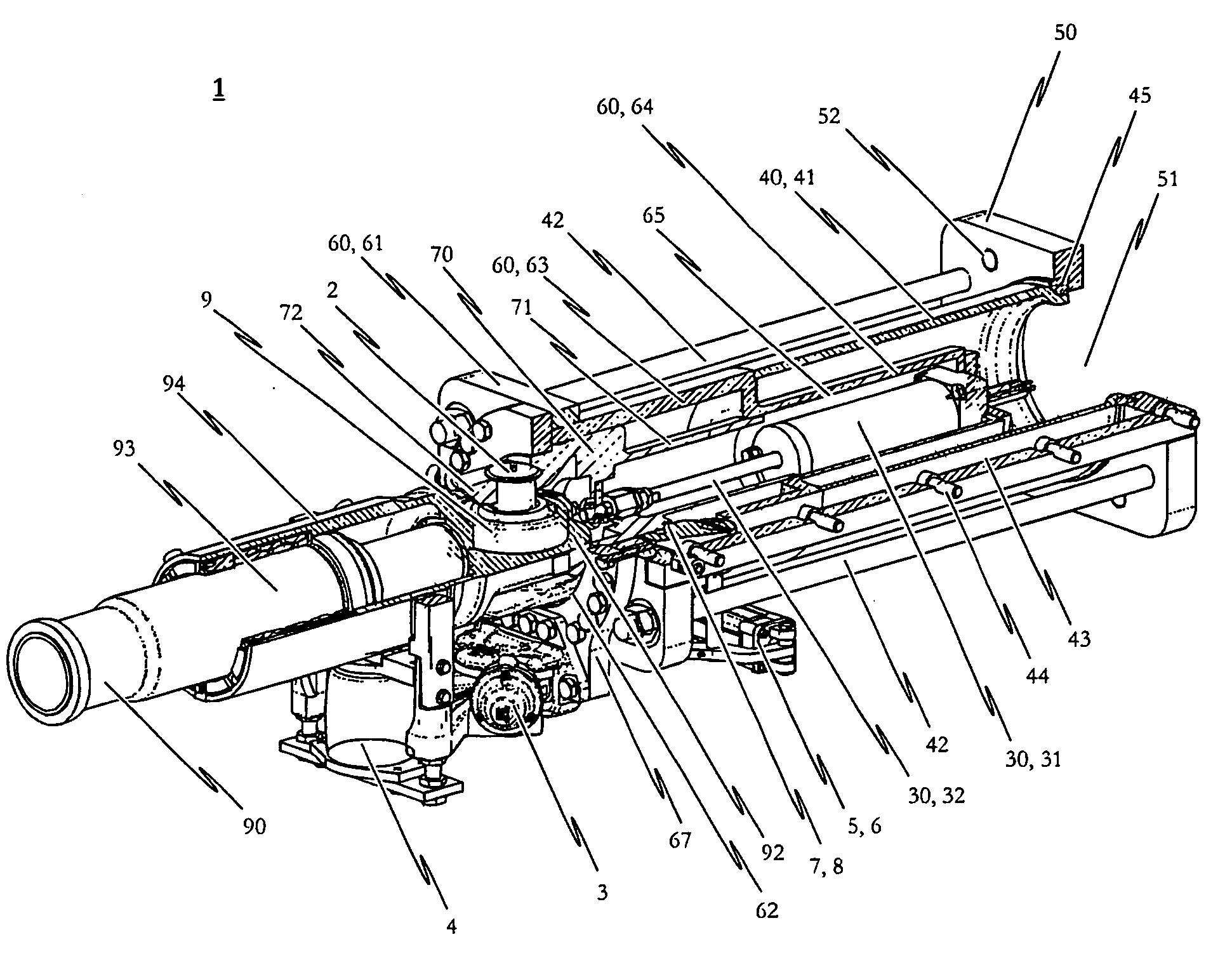
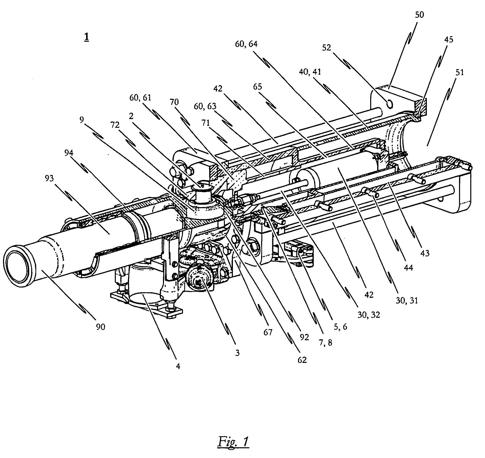
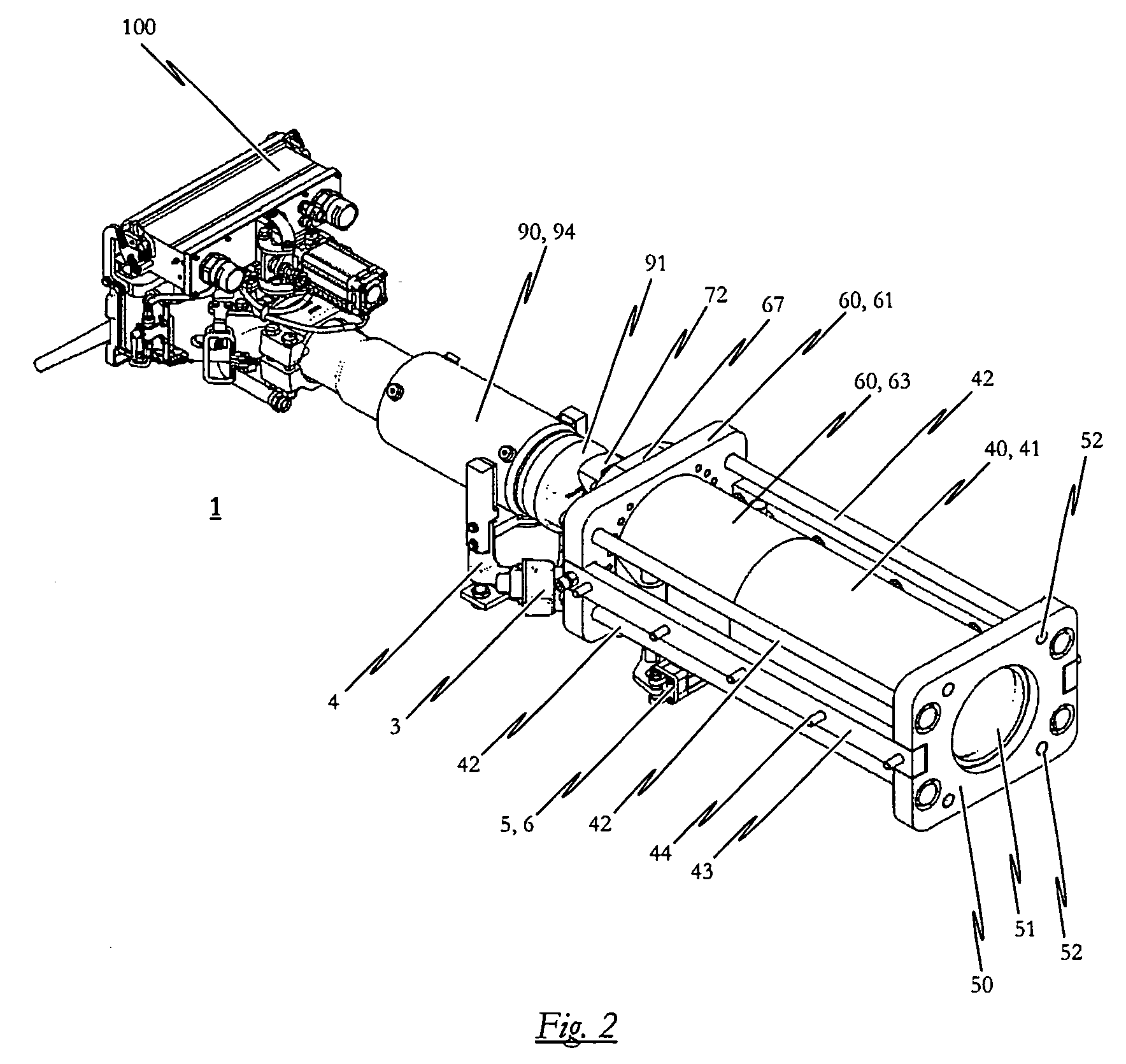
[0050]One embodiment of the inventive central buffer coupling will be described in the following with particular reference being made to FIGS. 1 to 4. The rear part of the central buffer coupling is thereby shown in FIG. 1 in a partly sectional perspective view. FIG. 2 shows a perspective view of the complete central buffer coupling in accordance with one embodiment while FIG. 3 depicts the bearing block and the shock absorber of one embodiment in a partly sectional side view. FIG. 4 shows a top plan view of the complete central buffer coupling according to one embodiment.

[0051]The automatic central buffer coupling 1, which is especially suited to a high-speed end car of a rail vehicle, includes a coupling head 100 which, for example, can be—as can be seen in particular in FIG. 6 of the attached drawings—a Type 10 Scharfenberg® coupling head. In FIG. 6, one embodiment of the inventive central buffer coupling is shown in a top plan view onto the end plate 101 of the coupling head 100...


PUM


Abstract

The invention relates to an automatic central buffer coupling having a coupling head, a coupling rod and a shock absorber including a destructively-configured force-absorbing member in the form of a deformable tube. The invention provides additional functionality of extendability and retractability to the coupling rod, the and for the central buffer coupling to include a controllable linear drive for the axial displacement of the coupling rod relative the fixing plate and for the bearing block to include a first bearing block component against which adjoins the coupling head-side end of the deformable tube, and a second bearing block component to which the vehicle-side end of the coupling rod is articulated, whereby the second bearing block component is axially displaceable relative the first bearing block component by means of the linear drive.

Description

CROSS-REFERENCE TO RELATED APPLICATIONS[0001]The present invention claims priority from European Patent Application No. 07002766.9, filed Feb. 8, 2007, the contents of which are herein incorporated by reference in their entirety.BACKGROUND OF THE INVENTION[0002]1. Field of the Invention[0003]The present invention relates to an automatic central buffer coupling for a vehicle, a rail-mounted vehicle in particular, including a coupling head, a coupling rod connected to the coupling head, a bearing block to which the vehicle-side end of the coupling rod is articulated so as to be horizontally pivotable, a fixing plate preferably attachable to the underframe of the vehicle to secure the central buffer coupling to the vehicle, and a shock absorber having a destructively-configured force-absorbing member in the form of a deformable tube with its coupling head-side end against the bearing block and its vehicle-side end against the fixing plate, whereby the shock absorber includes a bolted c...

Claims


Application Information

Patent Timeline
Patent Type & Authority Applications(United States)
IPC IPC(8): B61G5/00
CPCB61D15/06B61G7/08B61G7/10
Inventor KEMPER, ANDREAS
Owner VOITH PATENT GMBH
Why Eureka
Try Eureka