Reel

a technology of ribs and flanges, which is applied in the field of ribs, can solve the problems of limiting the amount of rigidity that can be raised by the formation of reinforcement ribs, and achieve the effects of suppressing the deformation of the flange caused by the winding tension of the recording tape, and increasing the rigidity of the hub

Active Publication Date: 2008-11-13
FUJIFILM CORP
View PDF13 Cites 5 Cited by
  • Summary
  • Abstract
  • Description
  • Claims
  • Application Information

AI Technical Summary

Benefits of technology

[0013]By such an aspect, since the engaging portion and the portion to be engaged that are used for positioning are the welding site, the rigidity of the hub may be increased.
[0014]In the above manner, ac

Problems solved by technology

However, there is a limit to the amount by which the rigi

Method used


Image

  • Reel
  • Reel
  • Reel

Examples


Embodiment Construction

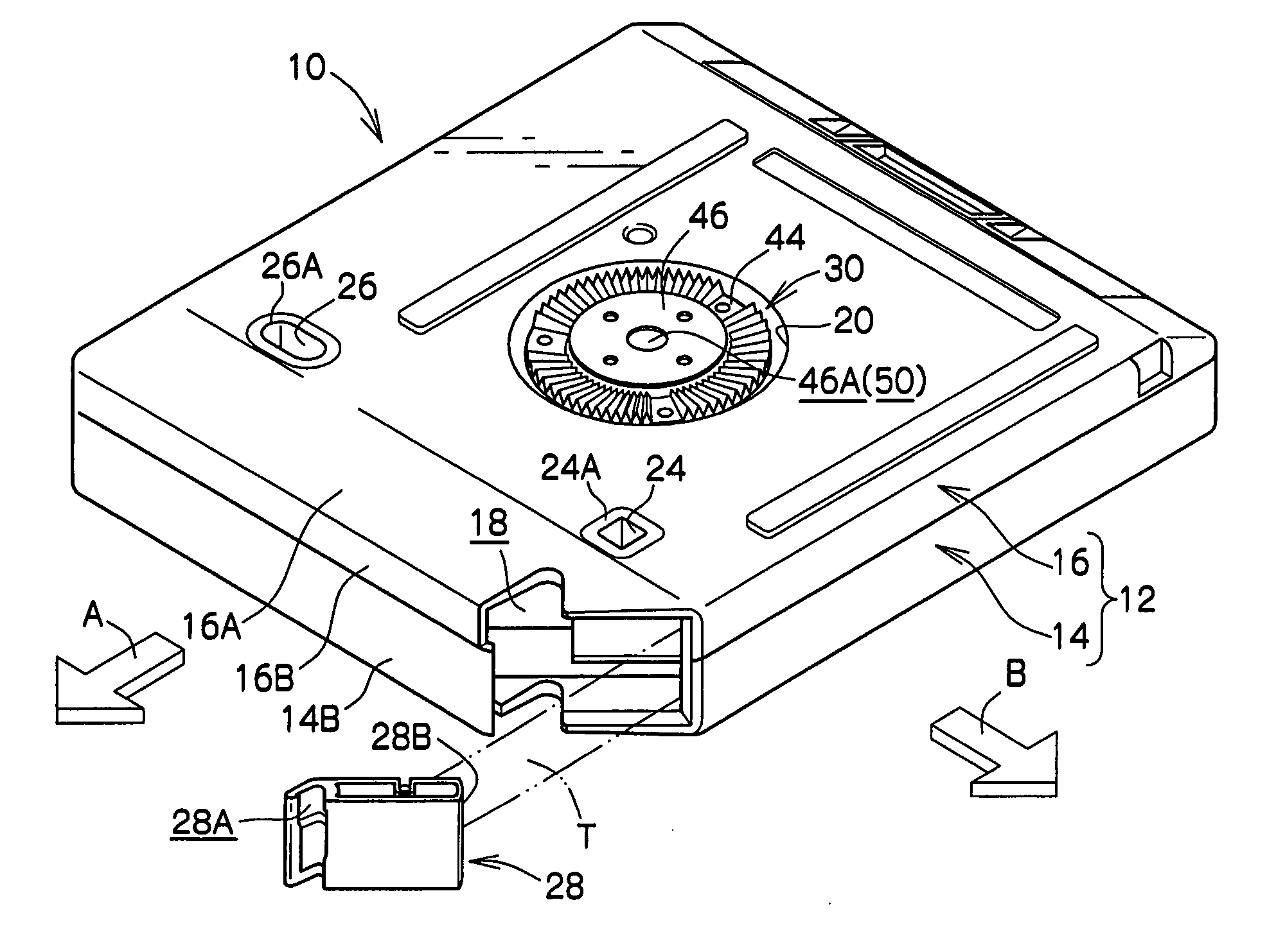
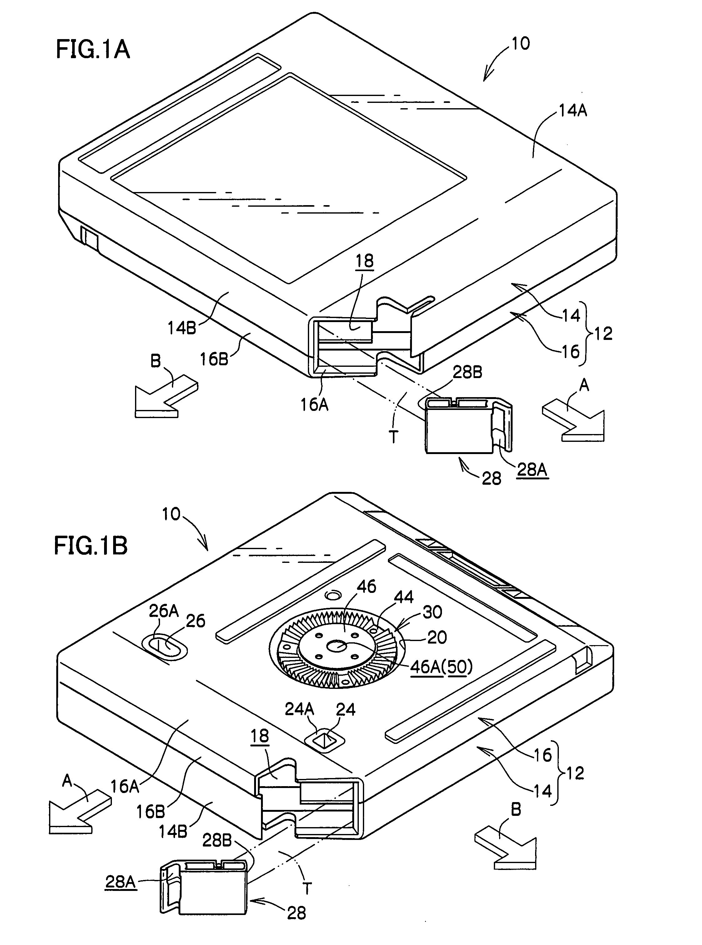
[0029]Explanation will now be given of details of an embodiment of the best mode of the present invention, with reference to an embodiment shown in the diagrams. First explanation will be given of the outline configuration of a recording tape cartridge 10. For ease of explanation, the direction of loading into a drive device of the recording tape cartridge 10 is shown by the arrow A, and this is designated as the front direction (front side). Also, the direction orthogonal to the direction of arrow A, shown by the arrow B, is designated as the right direction (right side) of the recording tape cartridge 10.

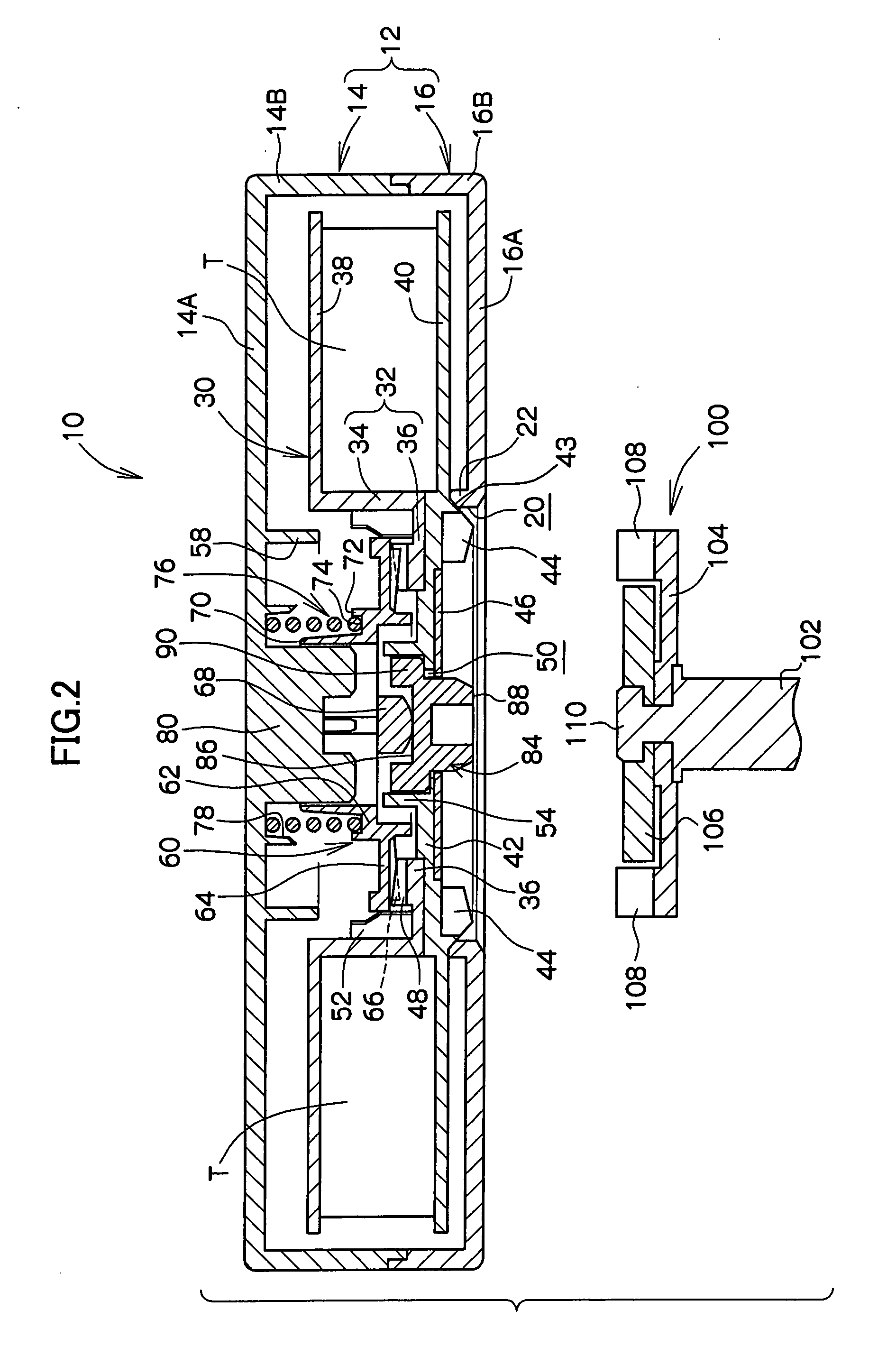
[0030]The recording tape cartridge 10 has a case 12, as shown in FIGS. 1 to 3. The case 12 is configured by an upper case 14 and a lower case 16, these being joined together. Specifically, the upper case 14 is configured such that a substantially frame-shaped peripheral wall 14B projects down from along the outer edge of a top panel 14A that is substantially rectangular in plan vi...


PUM


Abstract

A reel is provided that may raise the rigidity of the hub, and suppress flange deformation that is caused by winding tension of recording tape. The reel is provided with: a cylindrical hub on which recording tape may be wound; a top flange extending integrally to the hub from a peripheral edge at one end portion of the hub; a bottom flange, including a bottom wall that has had a reel plate fixed thereto, the bottom flange being welded to a portion of the hub at the opposite end of the hub to the end of the top flange, the welding site being within the region where the reel plate is fixed.

Description

CROSS-REFERENCE TO RELATED APPLICATION[0001]This application claims priority under 35 U.S.C 119 from Japanese Patent Application No. 2006-132334, the disclosure of which is incorporated by reference herein.BACKGROUND OF THE INVENTION[0002]1. Field of the Invention[0003]The present invention relates to a reel for winding recording tape thereon, such as magnetic tape or the like mainly used as a computer recording and reproduction medium.[0004]2. Description of the Related Art[0005]Conventionally, recording tape cartridges are known for winding recording tape, such as magnetic tape of the like used as a data recording / reproducing medium (data backup) such as for computers, onto a synthetic resin reel, with a single of these reels being stored in a case. These recording tape cartridge reels are, for example, formed by integrally forming a bottom flange and a hub, and welding an annular top flange at the top peripheral surface of the hub.[0006]In such a configuration of reel, deformatio...

Claims


Application Information

Patent Timeline
IPC IPC(8): G11B23/107
CPCG11B23/043G11B23/044G11B23/107
Inventor MORI, YASUHIROASHIKAWA, TERUO
Owner FUJIFILM CORP
Why Eureka
Try Eureka