Polarization Gratings in Mesogenic Films

Active Publication Date: 2008-11-13
STICHTING DUTCH POLYMER INST
View PDF6 Cites 114 Cited by
  • Summary
  • Abstract
  • Description
  • Claims
  • Application Information

AI Technical Summary

Benefits of technology

[0011]One object of the present invention is to overcome the above-mentioned problems of the prior art and to provide polarization gratings which are easy to produce and which exhibits high d

Problems solved by technology

In fact, this surface relief grating often degrades the unique diffraction properties of polarization gratings since the properties of both are superimposed.
Azo-containing materials are colored in the visible so the range of wavelength applicability is limited.
In addition, the long-term stability is usually limited, especially when the grating is

Method used


Image

  • Polarization Gratings in Mesogenic Films
  • Polarization Gratings in Mesogenic Films
  • Polarization Gratings in Mesogenic Films

Examples


Example

Example 1

Manufacture of a Single Layer Polarization Grating

[0167]To obtain a polarization grating, a photo-alignment material Vantico Star-Align 2110 was spincast onto a borosilicate glass substrate to form a thin, ˜50 nm, film.

[0168]The glass substrate was placed on a UV-absorber, a polycarbonate sheet and a index matching fluid film, to minimize back-surface reflections.

[0169]The photo-alignment film was then in a standard holographic setup exposed to two superimposed laser-beams of 351 nm at ˜9 J / cm2, one right handed and one left handed circularly polarized, each with an angle of incidence of 1.18°, and an angle of 2.36° separating the two beams. The polarization hologram formed in this holographic setup was thus recorded in the photo-alignment film.

[0170]Onto the photo-alignment layer, a polymerizable liquid crystal composition (RMM34 Eutectic mixture, Merck) was spincoated (Convac Spinner, 60 s at 2500 rpm) yielding a layer thickness of about 1.4 μm. To align the liquid crysta...

Example

Example 2

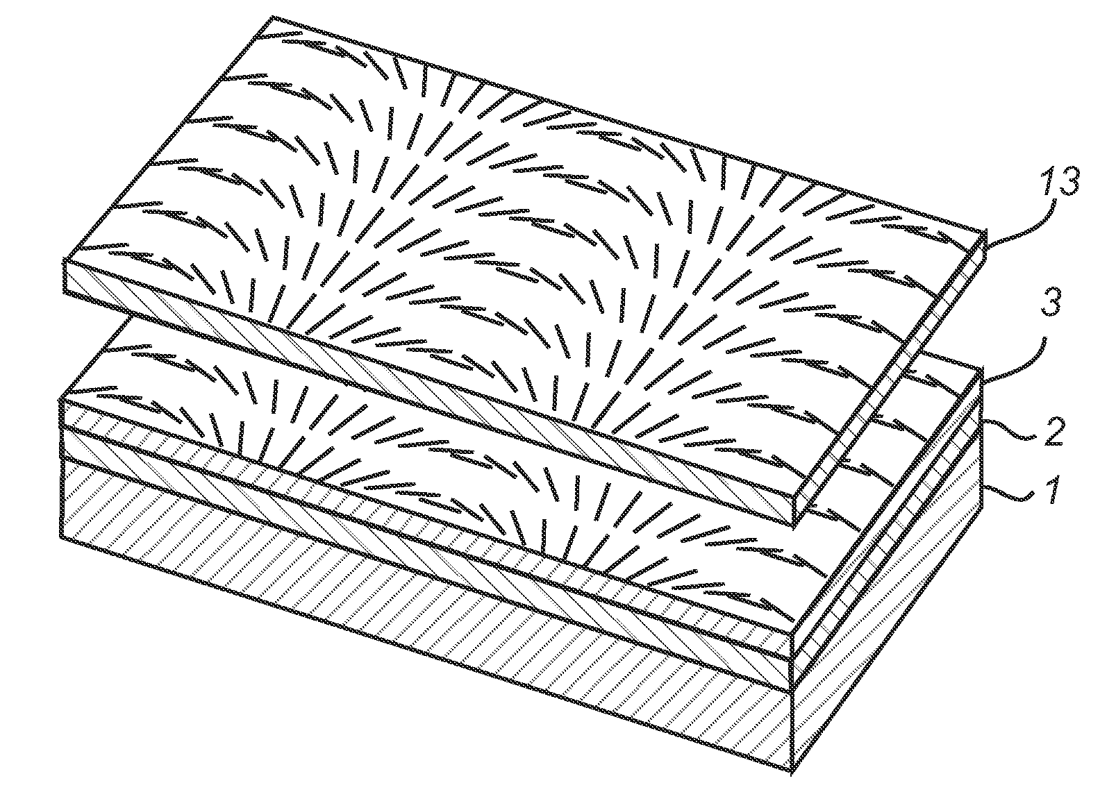
Manufacture of a Double Layer Polarization Grating

[0172]A polarization grating was manufactured as in example 1, as in example 1, however with an angle of 6.70° separating the beams.

[0173]Onto the photo-alignment layer, a polymerizable mesogen composition (RMM34, as in example 1) was aligned and polymerized to form a 1 μm thick solid film where the optical axis exhibits a repeating spiral pattern.

[0174]After polymerization of the first mesogen composition, a second mesogen composition (RMM34, as above) was coated onto the first, whereby it was aligned to the repeating spiral optical axis pattern of the first composition and polymerized to form a 1.2 μm thick solid layer.

[0175]The resulting double layer film was placed between crossed polarizers, and a photograph of this is shown in FIG. 5b, where the scale mark is 10 μm, and the grating period Λ is ˜3 μm.

[0176]The total thickness d of the formed polarization grating is 2.2 μm, and thus, this film widely exceeds the approxim...

Example

Example 3

Switchable Polarization Grating

[0178]Two borosilicate glass substrates was coated with a photo-alignment film as in example 1, and was arranged to as a closed cell structure with the alignment films facing each other. The cell spacing was 5.1 μm. The cell was filled with cyclohexane and then, in a standard holographic setup, exposed to two superimposed laser-beams of 351 nm at ˜10 J / cm2, one right handed and one left handed circularly polarized, with an angle of 2.28° separating the two beams.

[0179]The polarization hologram formed in this holographic setup was thus recorded in both the photo-alignment films. The cyclohexane was evaporated from the cell, and the cell was subsequently filled with a liquid crystal composition (E7, Merck), which was aligned by both the alignment films.

[0180]A transparent electrode was arranged on the outside of each substrate, and light of 633 nm was passed through the cell. The first order diffraction efficiency was measured as a function of t...


PUM

PropertyMeasurementUnit
Angleaaaaaaaaaa
Compositionaaaaaaaaaa
Magnetic fieldaaaaaaaaaa

Abstract

A polarization grating comprising a polarization sensitive photo-alignment layer (2) and a liquid crystal composition (3) arranged on said photo-alignment layer is provided. An alignment pattern, corresponding to the polarization pattern of a hologram, is recorded in the photo-alignment layer, and the liquid crystal composition is aligned on the photo-alignment layer. As the origin for the alignment of the liquid crystal composition is a polarization hologram recorded in a photo-alignment layer, an essentially defect-free pattern can be obtained with this approach.

Description

TECHNICAL FIELD[0001]The present invention relates to novel polarization gratings, as well as areas of application for such novel polarization gratings.TECHNICAL BACKGROUND[0002]Conventional diffraction gratings operate by periodically modulating the phase or amplitude of light propagating through them, potentially splitting incident light into multiple diffraction orders.[0003]Polarization gratings, which periodically modulate the polarization state of light traveling through them, have been known since the 1970s, when initial publications about the more general case of polarization holograms appeared in Soviet journals.[0004]It was soon recognized that the most compelling advantage of polarization gratings over conventional diffraction gratings was the possibility to control the polarization state of the diffracted orders while at the same time making the efficiency in each order dependent on the polarization of the incident light. Initial success at reducing the theory of polariz...

Claims


Application Information

Patent Timeline
IPC IPC(8): G02F1/1337G02B5/30
CPCG02B5/1833G02B5/3016G02B5/32G02B27/283G02F2203/07G02F1/13342G02F1/133788G02F2201/305G02F1/1323G02B5/30G02F1/1337
Inventor ESCUTI, MICHAEL J.SANCHEZ, CARLOSBASTIAANSEN, CORNELIS W.M.BROER, DIRK J.
Owner STICHTING DUTCH POLYMER INST
Why Eureka
Try Eureka