
Light fixtures and lighting devices

a technology of lighting devices and light fixtures, applied in the field of light fixtures, can solve the problems of reducing the effect of limiting the distance above the ceiling, and occupants' perception of glare and distracting, and achieve the effect of reducing the striation or hot spots projected on the walls

Active Publication Date: 2008-11-13
IDEAL IND LIGHTING LLC
View PDF49 Cites 284 Cited by
  • Summary
  • Abstract
  • Description
  • Claims
  • Application Information

AI Technical Summary

Benefits of technology

[0011]It would be desirable to provide a luminaire which ensures that the luminous surfaces are revealed in a controlled and comfortable way from all potential viewing angles. In addition, it would be desirable to provide a luminaire in which maximum luminances are not greater than amounts that will create discomfort glare. In addition, it would be desirable to provide a luminaire wherein as an observer moves closer to or further from a luminaire, the changes in luminances of the fixture occur gradually to ensure comfort and to minimize striations or hot spots projected on walls. Further, it would be desirable to provide a luminaire wherein luminance ratios of the luminaire when viewed while stationary are balanced, and significant changes do not happen over relatively small distances. In accordance with some aspects of the present inventive subject matter, there are provided devices with such properties.
[0094]In some lighting devices according to the present inventive subject matter, efforts are made to maximize the heat transfer area of the lighting device and / or the overall heat capacity of the lighting device, in particular, by maximizing the area of the components with which the heat sink (which is thermally coupled to the solid state light emitter(s)) is thermally coupled. The expression “thermally coupled”, as used herein, refers to components which readily transfer heat therebetween, e.g., components which are in contact with each other via a heat transfer gasket, thermal grease and / or thermal adhesive.

Problems solved by technology

A further challenge with solid state lighting arises from the relatively high light output from a relatively small area provided by solid state emitters.
Such a concentration of light output may present challenges in providing solid state lighting systems for general illumination in that, in general, large changes in brightness in a small area may be perceived as glare and distracting to occupants.
Yet another challenge with providing a solid state lighting system for troffer application relates to the distance the luminaire may extend above the ceiling tile.
While the area above a suspended ceiling may in many cases be quite deep, in some applications there may be obstructions or other constraints that limit the distance above the ceiling which the luminaire may extend.
Such restriction in height may present difficulties in providing luminaires with a high shield angle, as such shield angles are typically provided by recessing the light source into the ceiling.

Method used


Image

  • Light fixtures and lighting devices
  • Light fixtures and lighting devices
  • Light fixtures and lighting devices

Examples


Embodiment Construction

[0102]The present inventive subject matter now will be described more fully hereinafter with reference to the accompanying drawings, in which embodiments of the inventive subject matter are shown. However, this inventive subject matter should not be construed as limited to the embodiments set forth herein. Rather, these embodiments are provided so that this disclosure will be thorough and complete, and will fully convey the scope of the inventive subject matter to those skilled in the art. Like numbers refer to like elements throughout. As used herein the term “and / or” includes any and all combinations of one or more of the associated listed items.

[0103]The terminology used herein is for the purpose of describing particular embodiments only and is not intended to be limiting of the inventive subject matter. As used herein, the singular forms “a”, “an” and “the” are intended to include the plural forms as well, unless the context clearly indicates otherwise. It will be further unders...


PUM


Abstract

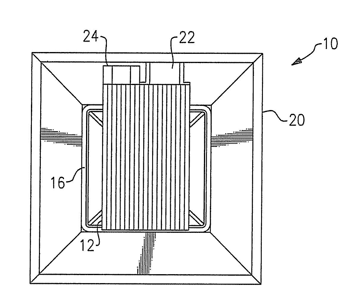
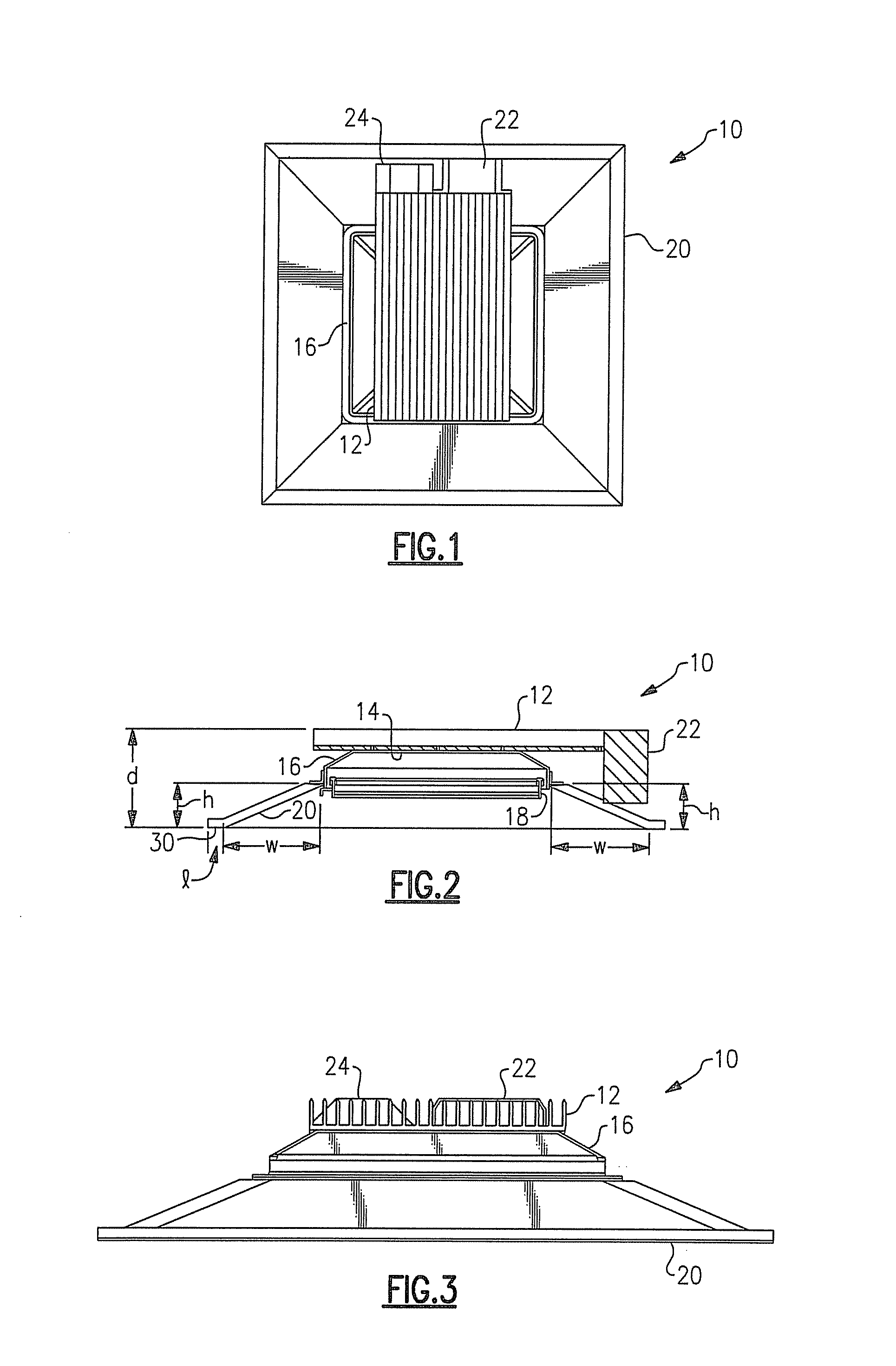
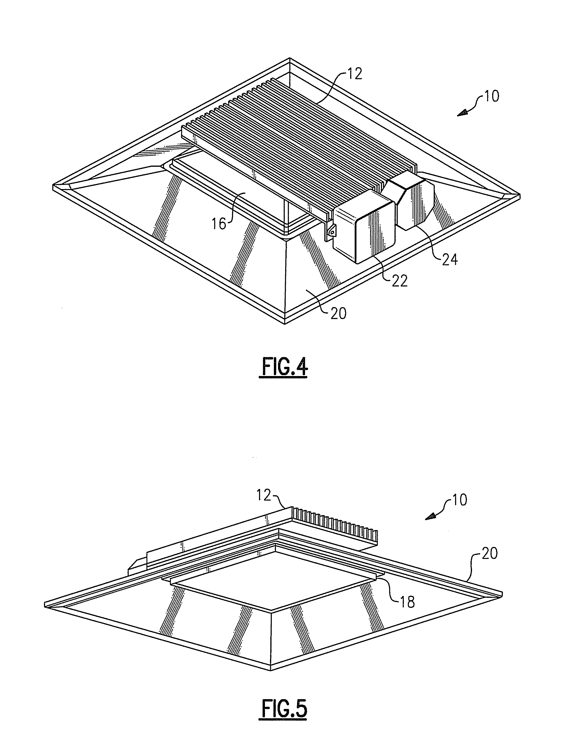
A lighting device comprises a heat sink, a housing mounted to and / or thermally coupled to the heat sink, a basket assembly attached to the housing, a solid state light emitter thermally coupled to the heat sink, and a baffle assembly attached to the housing. Also, a lighting device comprising a basket assembly and a baffle assembly. In some embodiments, the basket assembly comprises a first member defining a first opening, a second member, a space between the first and second members, and lenses in the opening and in the space. In some embodiments, the heat sink extends farther in a first direction in a first plane than a largest dimension of the housing in any plane which is parallel to the first plane. In some embodiments, at least one additional component (e.g., a power supply module or a junction box) is in contact with the heat sink element.

Description

CROSS-REFERENCE TO RELATED APPLICATIONS[0001]This application claims the benefit of U.S. Provisional Patent Application No. 60 / 916,407, filed May 7, 2007, the entirety of which is incorporated herein by reference.[0002]This application claims the benefit of U.S. Provisional Patent Application No. 61 / 029,068, filed Feb. 15, 2008, the entirety of which is incorporated herein by reference.[0003]This application claims the benefit of U.S. Provisional Patent Application No. 61 / 037,366, filed Mar. 18, 2008, the entirety of which is incorporated herein by reference.FIELD OF THE INVENTION(S)[0004]The present inventive subject matter relates to a light fixture. In some aspects, the present inventive subject matter relates to a light fixture for use with solid state light emitters, e.g., light emitting diodes (LEDs).BACKGROUND OF THE INVENTION(S)[0005]One particular type of light fixture is known as a lay-in luminaire, or a troffer. The lensed troffer is the most popular lay-in sold today. It...

Claims


Application Information

Patent Timeline
Patent Type & Authority Applications(United States)
IPC IPC(8): F21V29/00F21V7/00F21V21/00
CPCF21S8/02F21V11/02F21V29/70F21Y2101/02F21K9/58F21V29/004F21V29/763F21V15/01F21Y2115/10F21V1/02F21V23/00
Inventor PICKARD, PAUL KENNETHTROTT, GARY DAVID
Owner IDEAL IND LIGHTING LLC
Learn More