Image forming apparatus

a technology forming apparatus, which is applied in the direction of electrographic process apparatus, thin material handling, instruments, etc., can solve the problems of difficult to achieve downsizing and cost reduction of image forming apparatus, and the fixation of duplex image formation becomes difficult, so as to prevent the reduction of the fixation accuracy of toner image and promote the downsizing of the image forming apparatus

Inactive Publication Date: 2008-11-13
CANON KK
View PDF8 Cites 18 Cited by
  • Summary
  • Abstract
  • Description
  • Claims
  • Application Information

AI Technical Summary

Benefits of technology

[0023]The object of the present invention is to provide an image forming apparatus capable of promoting downsizing of the image forming apparatus and of preventing reduction in fixation accuracy of a toner image.

Problems solved by technology

In this case, however, the following problem occurs.
Accordingly, the fixation in the duplex image formation becomes difficult in some cases.
As described above, the conventional image forming apparatus has a problem of that a length of the duplex conveying path 682 has to be adjusted to a length of the recording material and it is difficult to achieve downsizing and cost reduction of the image forming apparatus.

Method used


Image

  • Image forming apparatus
  • Image forming apparatus
  • Image forming apparatus

Examples


first embodiment

Image Forming Apparatus of First Embodiment

[0042]FIGS. 1 to 7 each illustrate the image forming apparatus according to the first embodiment of the present invention.

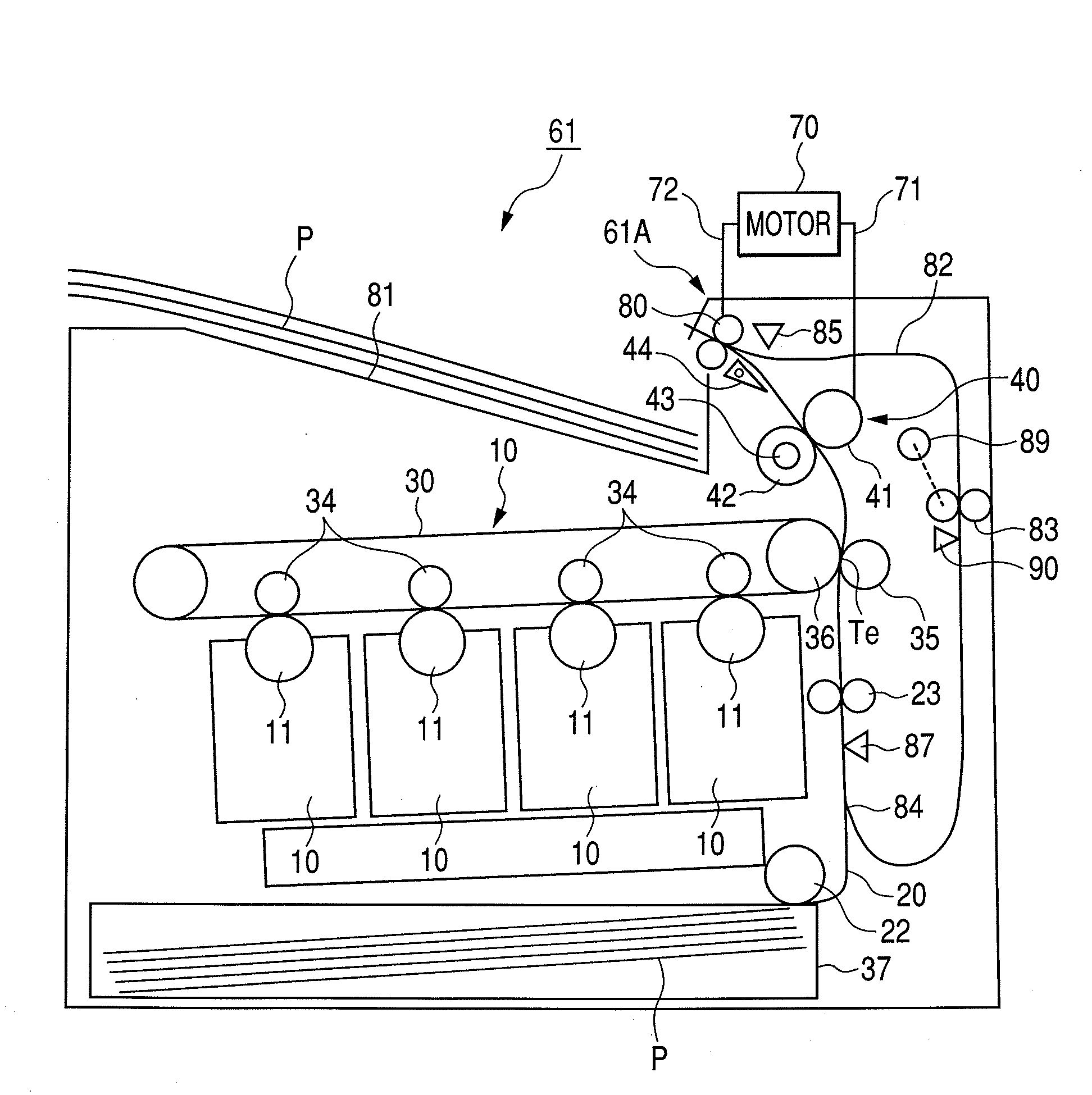
[0043]FIG. 7 is a sectional view of the image forming apparatus according to the first embodiment of the present invention, taken along a conveying direction of a recording material. An operation of an image forming apparatus 61 is schematically described.

[0044]In the image forming apparatus 61, first, latent images are formed on photosensitive drums 11 of image bearing members by using light, magnetism, or electric charge, and the latent images are visualized as toner images. On the plurality of photosensitive drums 11 constituting an image forming portion 10 and corresponding to various colors, there is disposed a belt-like intermediate transferring body 30 circulating by being pulled by multiple rollers. On an inner side of the intermediate transferring body 30, there are arranged primary charging devices 34. The inte...

second embodiment

Image Forming Apparatus of Second Embodiment

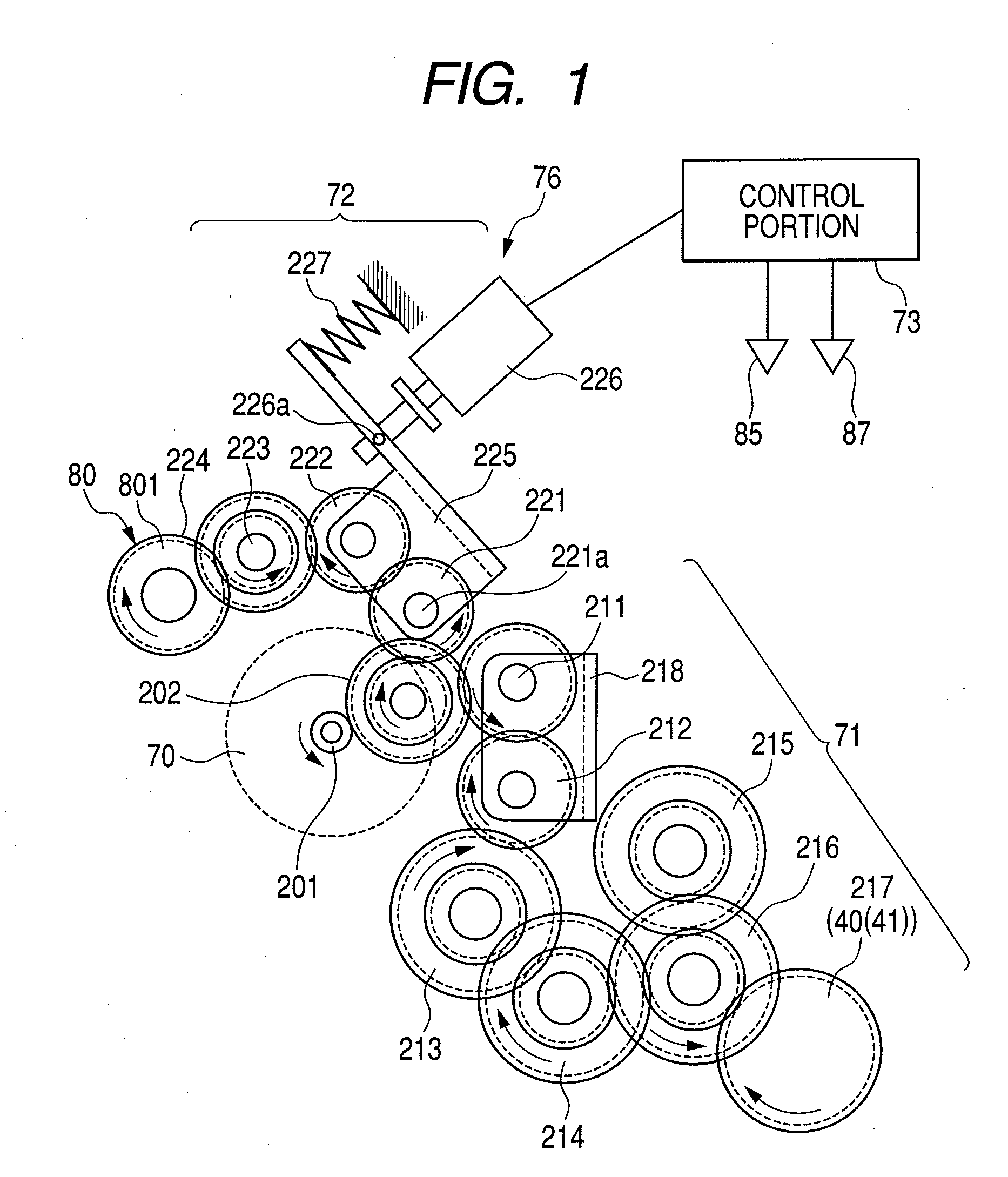
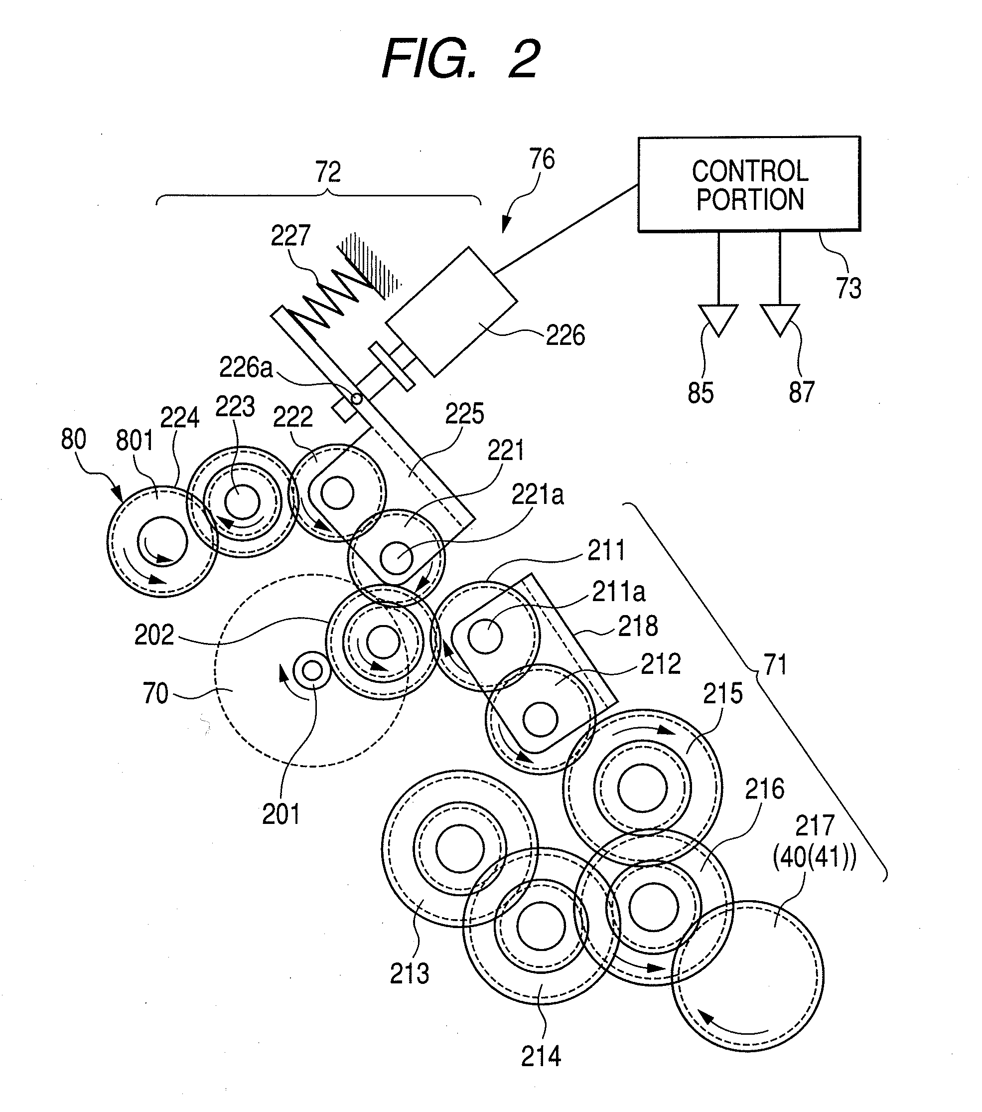
[0085]In FIG. 8, an image forming apparatus 62 has a clutch 228 serving as a blocking portion which is interposed between the gear 224 of the discharge driving train 172 and the metal cored bar 801a of the drive roller 801, so that rotation of the motor 70 can be blocked between the discharge reversing roller pair 80 and the motor 70. Note that, the clutch 228 may be provided between the gears 221 to 224. The clutch 228 and the control portion 73 constitute a stopping portion 77 serving as a stopping unit.

[0086]In this case also, the clutch 228 is actuated when the control portion 73 issues the operation signal 74 in response to the leading end detection signal 88 and the rear end detection signal 86, thereby preventing the rotation of the motor 70 from being transmitted to the discharge reversing roller pair 80. As a result, the drive roller 801 becomes rotatable. Similarly to the case of the first embodiment of the present invention, the...

third embodiment

Image Forming Apparatus of Third Embodiment

[0088]In FIG. 9, in an image forming apparatus 63, a stopping portion 78 serving as a stopping unit can moves the driven roller 802 apart from the drive roller 801 of the discharge reversing roller pair 80, thereby stopping a refeeding operation (an operation of conveying the recording material) of the discharge reversing roller pair 80.

[0089]In the image forming apparatus 63 of this embodiment, the gear trains for rotating the fixing device 40 and the discharge reversing roller pair 80 are the same as the gear trains illustrated in FIGS. 13 and 14. A description is made of the image forming apparatus 63 of this embodiment with illustration of only characteristic portions thereof, and illustration and descriptions of other portions are omitted.

[0090]The cored bar 802a of the driven roller 802 of the discharge reversing roller pair 80 has both ends supported by the bearings 803, and a pressurization releasing support plate 806 is engaged wit...


PUM

PropertyMeasurementUnit
lateral lengthaaaaaaaaaa
rotational forceaaaaaaaaaa

Abstract

An image forming apparatus includes an image forming portion which forms a toner image on a sheet; a fixing rotary member pair which fixes the toner image onto the sheet; a reversing rotary member pair capable of performing a refeeding operation in which, in order to form a toner image on another surface of the sheet having one surface on which an image has been formed, the reversing rotary member pair rotates forward and then rotates backward to refeed the sheet toward the image forming portion; and a drive portion which drives the fixing rotary member pair and the reversing rotary member pair by a common drive source, wherein the drive portion can continue to rotate the fixing rotary member pair even when the drive portion stops the refeeding operation of the reversing rotary member pair.

Description

BACKGROUND OF THE INVENTION[0001]1. Field of the Invention[0002]The present invention relates to an image forming apparatus for forming images on both surfaces of a recording material (sheet).[0003]2. Description of the Related Art[0004]Conventionally, as an image forming apparatus adopting electrostatic recording, or electrophotographic process, there is provided an image forming apparatus capable of forming images on both surfaces of a recording material. In the image forming apparatus of this type, an image is formed on one surface of the recording material in an image forming portion, the recording medium is then reversed, and an image is also formed on another surface of the recording material again in the image forming portion.[0005]FIG. 12 is a sectional view taken along a conveying direction of the recording material in the conventional image forming apparatus capable of forming images on both surfaces of the recording material. FIGS. 13 and 14 are views each illustrating ge...

Claims


Application Information

Patent Timeline
Patent Type & Authority Applications(United States)
IPC IPC(8): G03G15/23B65H29/00
CPCB65H29/12B65H2301/33312B65H2403/422B65H2403/72B65H2403/80B65H2403/942B65H2801/06G03G15/234G03G15/6579
Inventor SAHARA, HIROSHIKATO, TAKAYUKI
Owner CANON KK
Why Eureka
Try Eureka