Expandable support device

a support device and expandable technology, applied in the field of expandable support devices, can solve the problems of cement mixture leakage from the bone, entering a dangerous location, spinal canal,

Inactive Publication Date: 2008-11-13
STOUT MEDICAL GROUP
View PDF4 Cites 355 Cited by
  • Summary
  • Abstract
  • Description
  • Claims
  • Application Information

AI Technical Summary

Problems solved by technology

The cement mixture can leak from the bone, potentially entering a dangerous location such as the spinal canal.
The cement mixture, which is naturally viscous, is difficult to inject through small diameter needles, and thus many practitioners choose to “thin out” the cement mixture to improve cement injection, which ultimatel

Method used


Image

  • Expandable support device
  • Expandable support device
  • Expandable support device

Examples


Embodiment Construction

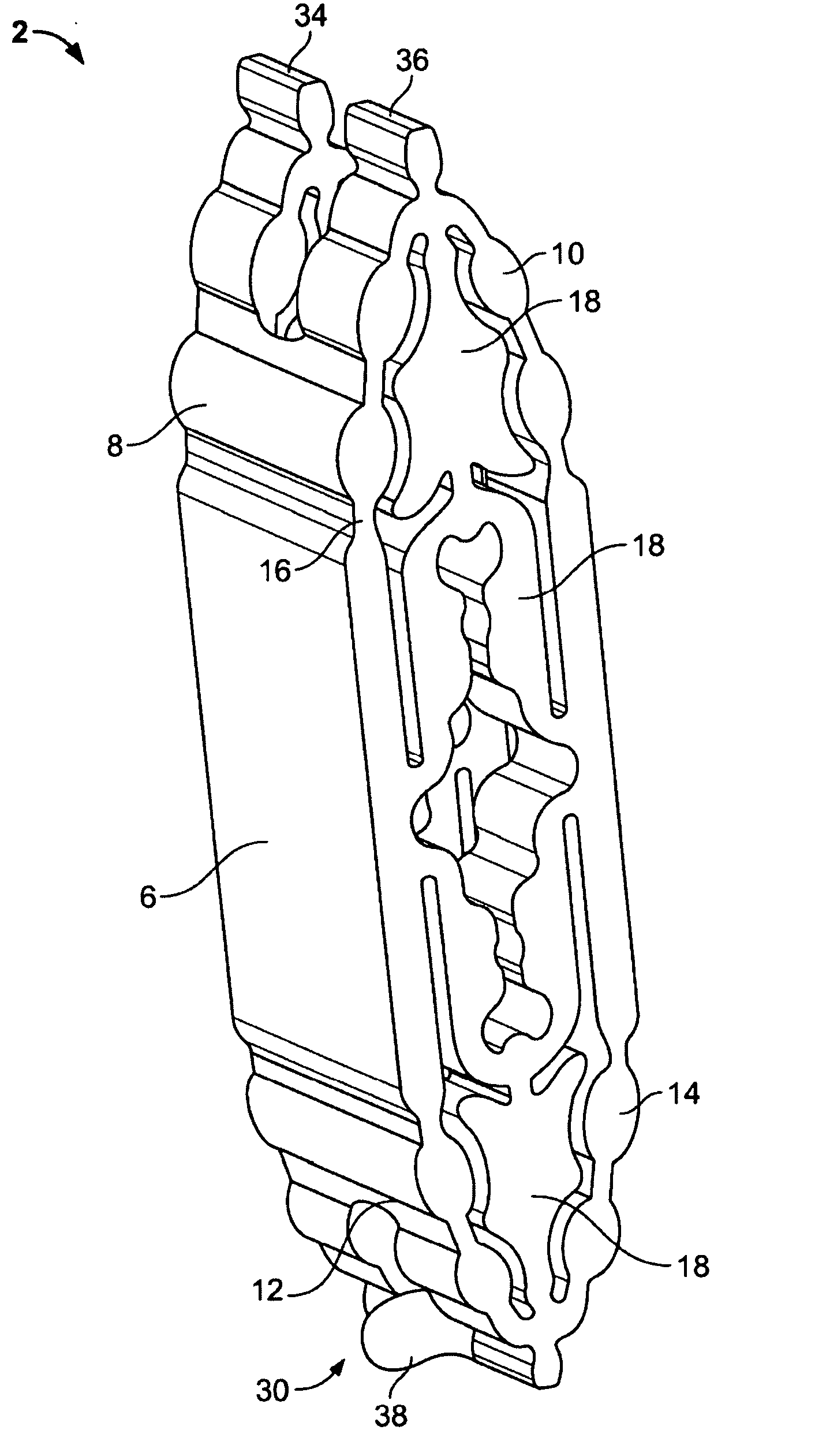
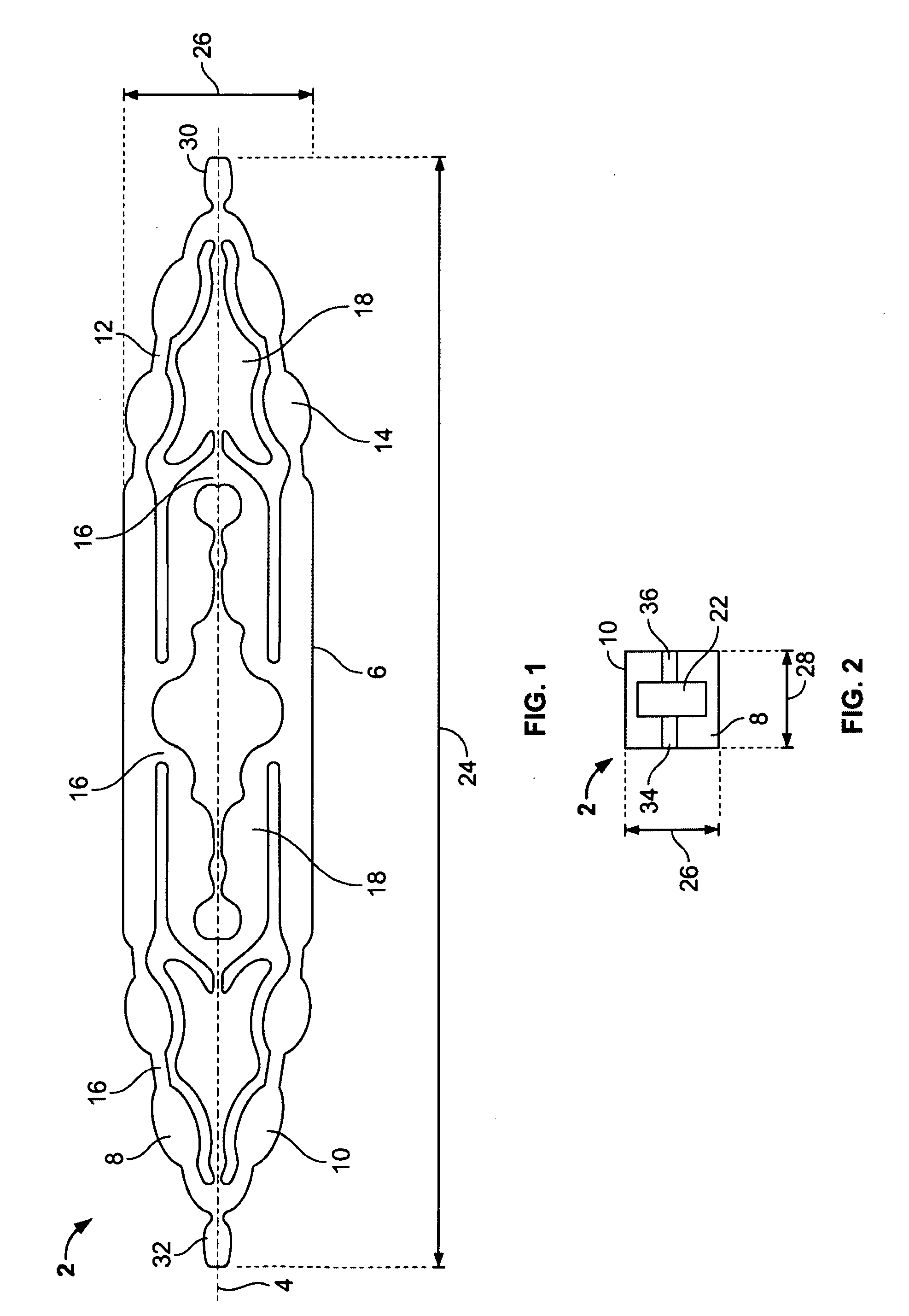
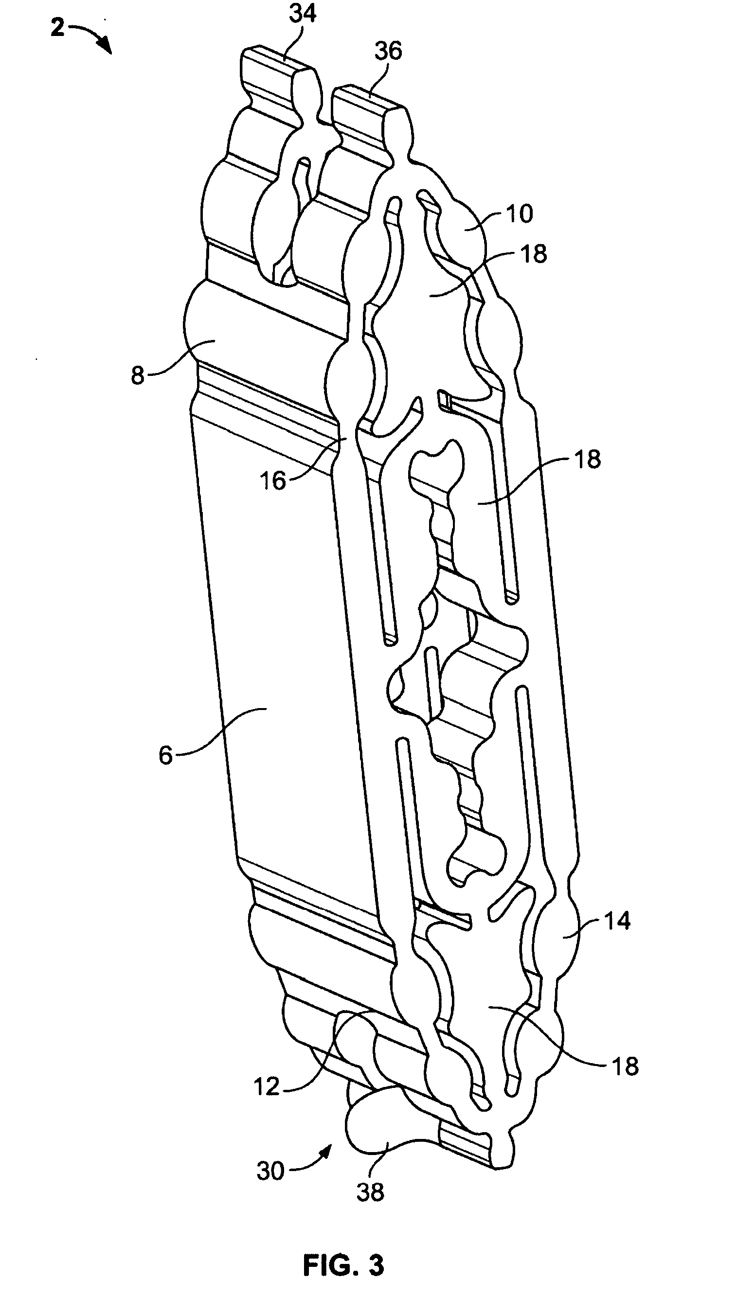
[0018]FIGS. 1 through 3 illustrate a biocompatible implant that can be used for tissue repair, for example for repair bone fractures such as spinal compression fractures, and / or repairing soft tissue damage, such as herniated vertebral discs. The implant can be an expandable support device 2. The expandable support device 2 can have a longitudinal axis 4. The expandable support device 2 can be in a first, contracted configuration, for example a radially contracted configuration. The expandable support device 2 can have a second, radially expanded configuration.

[0019]The expandable support device 2 can have one, two or more plates, such as side 6, proximal and distal plates. The side 6, proximal and distal plates can be split into multiple plates, for example a proximal first plate 8 and a proximal second plate 10, also for example, a distal first plate 12 and a distal second plate 14. The distal first plate 12 can be rotationally connected to the distal second plate 14. The proximal...


PUM


Abstract

A device for providing support for biological tissue is disclosed. The device can expand and be implanted in lieu of removed or otherwise missing bone, such as a vertebra, and/or soft tissue, such as a intervertebral disc. The device can be configured to radially expand in a single plane when the device is longitudinally contracted. Methods for using the device are also disclosed.

Description

CROSS-REFERENCE TO RELATED APPLICATION[0001]This application is a continuation of PCT International Application No. PCT / US2006 / 062339, filed Dec. 19, 2006 which claims the benefit of U.S. Provisional Application No. 60 / 752,185, filed Dec. 19, 2005, which are both incorporated herein by reference in their entireties.BACKGROUND OF THE INVENTION[0002]This invention relates to devices for providing support for biological tissue, for example to repair spinal compression fractures, and methods of using the same.[0003]Vertebroplasty is a therapy used to strengthen a broken vertebra that has been weakened by disease, such as osteoporosis or cancer. Vertebroplasty is often used to treat compression fractures, such as those caused by osteoporosis, cancer, or stress. Vertebroplasty is also often performed as an image-guided, minimally invasive procedure.[0004]Vertebroplasty is often performed on patients too elderly or frail to tolerate open spinal surgery, or with bones too weak for surgical ...

Claims


Application Information

Patent Timeline
IPC IPC(8): A61M29/00A61F2/44
CPCA61B17/70A61B17/8858A61F2/4455A61F2002/2817A61F2002/30092A61F2002/30471A61F2002/30579A61F2002/30677A61F2002/4435A61F2002/4475A61F2210/0014A61F2220/0091A61F2310/00017A61F2310/00023A61F2310/00029A61F2002/30593
Inventor GREENHALGH, E. SKOTTROMANO, JOHN-PAUL
Owner STOUT MEDICAL GROUP
Why Eureka
Try Eureka