

Shaped Charge and a Perforating Gun
a perforating gun and shaped charge technology, applied in the direction of explosive charges, weapons, borehole/well accessories, etc., can solve the problems of clogging the perforation, affecting the flow of fluid through the perforation, and still not entirely satisfactory in the oilfield application. , to save the time of operating the rig for other operations
- Summary
- Abstract
- Description
- Claims
- Application Information
AI Technical Summary
Benefits of technology
Problems solved by technology
Method used
Image

Examples
first embodiment
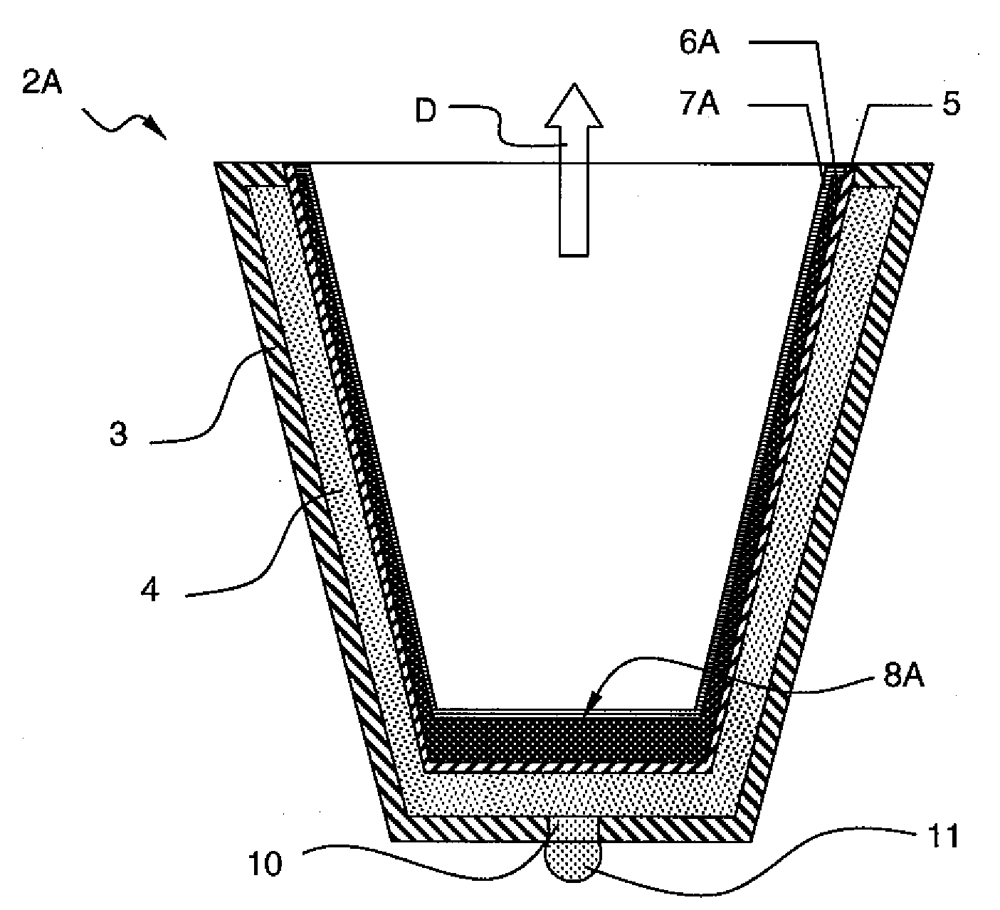
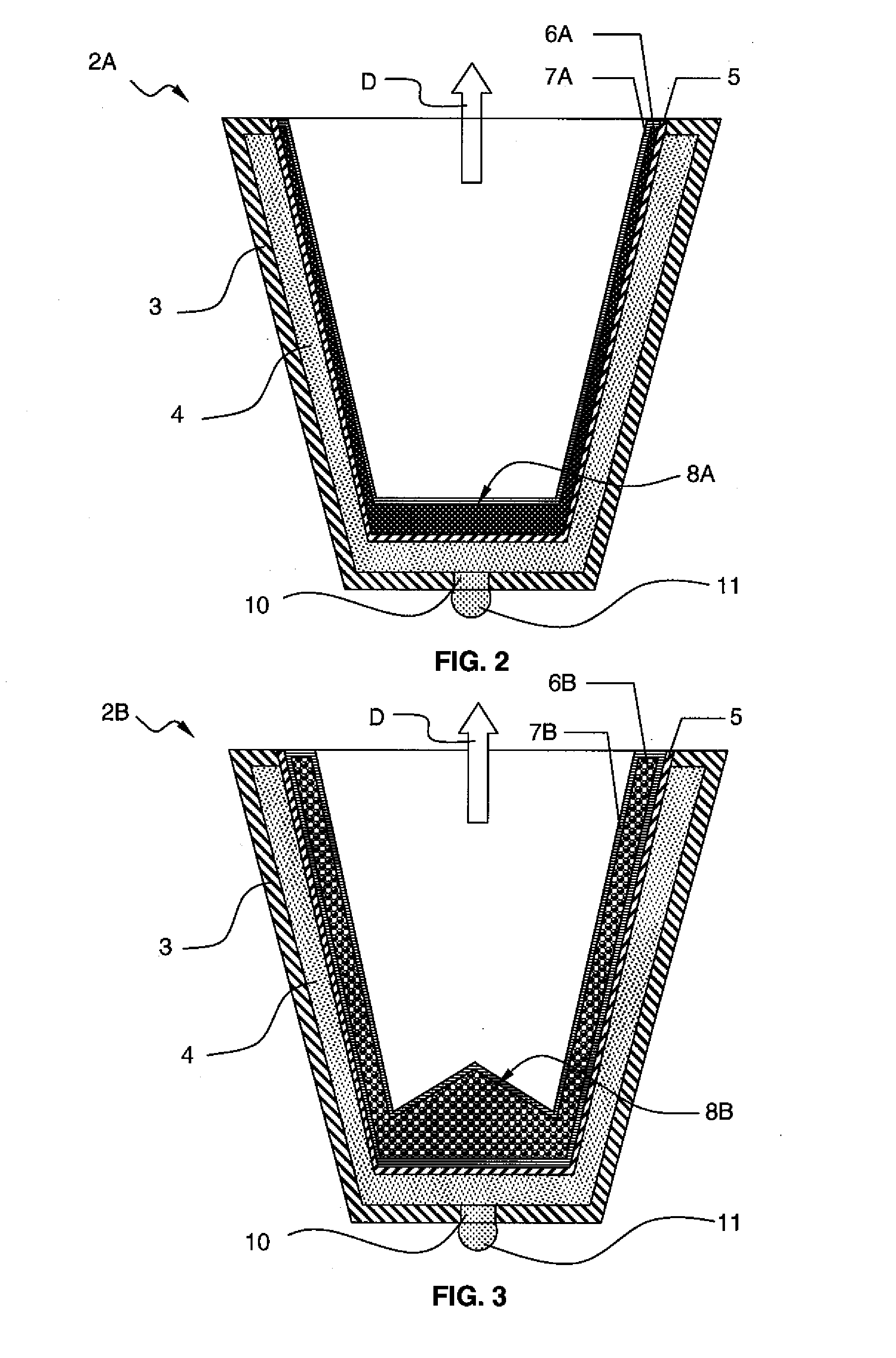
[0023]FIG. 2 is a cross-section view into a shaped charge according to the invention.
[0024]The shaped charge of the first embodiment 2A comprises a shell 3, an explosive charge 4, a liner 5, an acid powder layer 6A, a protective liner 7A and a detonating link element 10.
[0025]The shell 3 is similar to a cup having a U-shape or cone shape. The shell supports the explosive material and is adapted to be housed in the perforating gun, or in a loading tube (not represented) of the perforating gun. Once the shaped charge is detonated, the shell acts as a confining element providing sufficient confinement to help in forming a perforating jet that is directed in the longitudinal direction (see arrow D in FIGS. 2 and 3). For this reason, the shell is made in a robust material, e.g. steel. The explosive charge 4 is made of an explosive material packed against the inner wall of the shell.
[0026]The detonating link element 10 goes through an opening of the shell 3 and couples the explosive charg...
second embodiment
[0032]FIG. 3 is a cross-section view into a shaped charge according to the invention.
[0033]The shaped charge of the second embodiment 2B comprises a shell 3, an explosive charge 4, a liner 5, an acid compound 6B, an encapsulating liner 7B and a detonating link element 10.
[0034]The elements of the second embodiment that are common with the first embodiment, namely the shell 3, the explosive powder 4, the liner 5 and the detonating link element 10 will not be further described.
[0035]The acid compound 6B may be made of spheres or micro-spheres filled with an acid. The acid may be in the physical state of a fluid, a gel or a solid.
[0036]The encapsulating liner 7B is a protective shell which encapsulates the spheres or micro-spheres and prevents water contact or deterioration of the spheres or micro-spheres before the beginning of the perforation operation. As an example, the protective shell may be polyethylene. The encapsulating liner 7B may have a uniform thickness all over the liner ...
PUM
 Abstract
Description
Claims
Application Information