Paper roll dispenser

a dispenser and paper roll technology, applied in the field of tissue roll mounts, to achieve the effect of reducing the incidence of tissue damage, minimizing the force, and facilitating the removal of the spent roll and the replacement by a new on

Inactive Publication Date: 2008-11-20
REILLY ROBERT E
View PDF0 Cites 4 Cited by
  • Summary
  • Abstract
  • Description
  • Claims
  • Application Information

AI Technical Summary

Benefits of technology

[0011]Those skilled in the art will appreciate that the foregoing combination allows for an interlocked retention of the mounts in their seats in the lower cavity with the corresponding foam blocks also fixed by compression therein. In this manner all the components needed for assembly are fully located in the lower cavity shell to be then covered by the upper shell, rendering the completion of the assembly both simple and expedient. It will be further appreciated by those skilled in the art that unlike a helical spring that varies exponentially with deflection in its compression forces, the resilience of an open-celled polymeric structure is generally flat, thus minimizing the forces on the edges of the tissue roll as it is pressed between the pivotally retracting mounts. The incidence of tissue damage and the convenience of removing the spent roll and replacement by a new one is thus greatly improved, particularly when the projecting mount edges are rounded further to reduce all concentrated points of contact. Of course, the foregoing assembly may be conveniently mounted onto a mounting bracket in a manner generally like that earlier described.
[0012]In this manner all the advantages and benefits of my prior tissue roll mounts are greatly enhanced in a structure that is conveniently fabricated and assembled into sanitary configuration characterized by a smooth and clean exterior.

Problems solved by technology

In a growing family household this rather cumbersome replacement process of the fresh tissue rolls is an event of some frequency and quite often the new roll is simply left loose and unmounted to clutter the various surfaces of a bathroom where they either unroll or get wet to become useless.

Method used


Image

  • Paper roll dispenser
  • Paper roll dispenser
  • Paper roll dispenser

Examples


Embodiment Construction

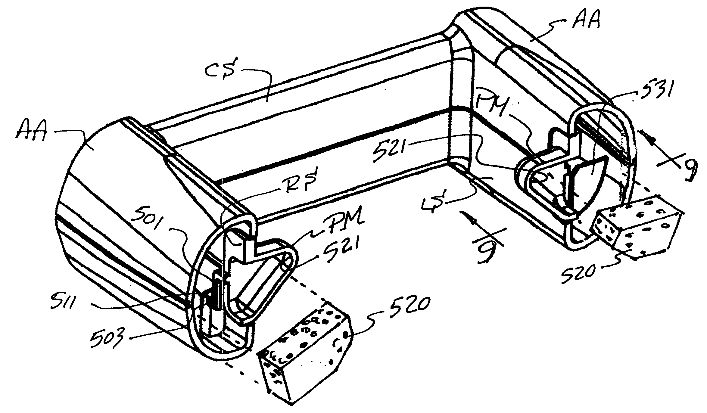
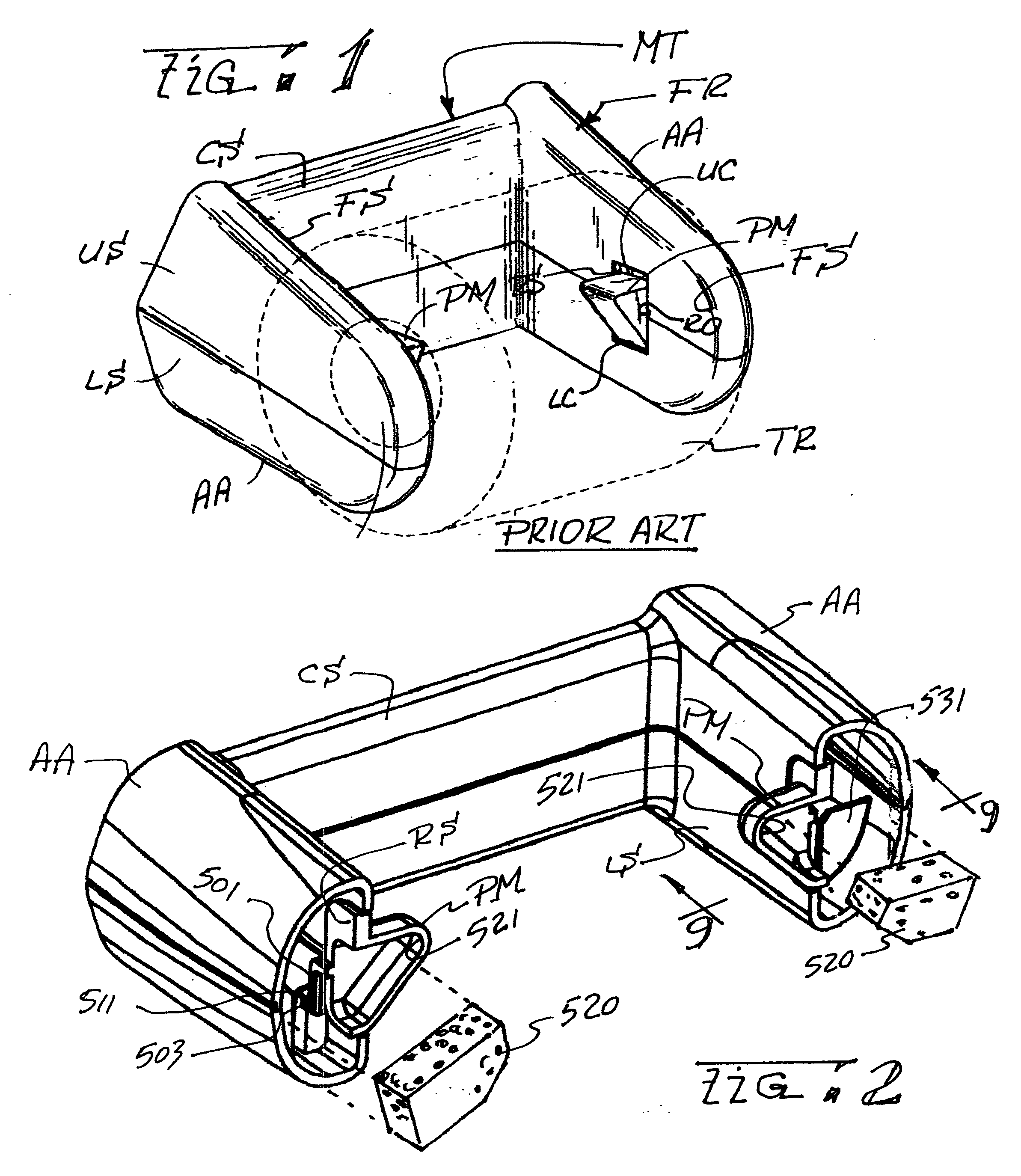
[0022]While I have earlier disclosed several inventive variants of a tissue roll mount assembly in my prior U.S. Pat. Nos. 6,189,828 and 6,386,478 respectively issued on Feb. 20, 2001, and May 14, 2002, and while the instant invention is useful with both the foregoing teachings its operative aspects are best explained in association with the illustrations in the '478 patent incorporated herein by reference and exemplified by the prior art illustration shown as FIG. 1. As shown in this illustration, a tissue roll mount assembly generally shown at MT comprises a generally U-shaped hollow frame FR formed by joining the peripheral edge of a hollow upper frame shell US to the periphery of a lower shell LS to cooperatively form a central structure CS conformed for attachment to a wall (not shown). A pair of hollow arm assemblies AA extending in cantilever from the ends of the central structure CS then form opposed face surfaces FS spaced to receive a tissue roll TR therebetween. Each of t...


PUM


Abstract

A tissue roll mount is conformed for convenient assembly by providing internal pivot seats subjacent the lower interior edges of each one of two opposed openings formed in the roll supporting arms. Each one of the pivot seats forming a pair is spaced relative the other by a dimension that is smaller than the spacing between the pivots at the ends of cantilevered pivot arms aligned along the vertical edges of a set of opposed pivotal mounts to capture the ends of the arms therein. A block of open-celled resilient foam is then inserted in each arm for capture in compression against the corresponding pivot mount.

Description

BACKGROUND OF THE INVENTION[0001]1. Field of the Invention[0002]The present invention relates to tissue roll mounts, and more particularly to improvements therein for rendering the fabrication and assembly thereof inexpensive and convenient while also reducing edge damage to the tissue rolls in the course of their replacement.[0003]2. Description of the Prior Art[0004]Tissue roll mounts have been known in the past, most frequently taking the form of an axially compressed spring loaded roller captured between two arms on which rolls of tissue are mounted to be replaced as the tissue is used up. To accommodate mounting the tissue on each roll is typically wound around a central tube segment into which the spring loaded roller is inserted, then compressed to fit between the arms and thereafter released to extend for capture of its extending ends in opposed recesses in each arm. In a growing family household this rather cumbersome replacement process of the fresh tissue rolls is an even...

Claims


Application Information

Patent Timeline
Patent Type & Authority Applications(United States)
IPC IPC(8): A47K10/40
CPCA47K10/40
Inventor REILLY, ROBERT E.
Owner REILLY ROBERT E
Why Eureka
Try Eureka