Proximity sensor and method for indicating a display orientation change

a proximity sensor and display technology, applied in the field of electronic devices, can solve problems such as the orientation of displayed information, and achieve the effects of convenient display orientation changes, increased usability and flexibility, and easy caus

Inactive Publication Date: 2008-11-20
WACOM CO LTD
View PDF12 Cites 120 Cited by
  • Summary
  • Abstract
  • Description
  • Claims
  • Application Information

AI Technical Summary

Benefits of technology

[0006]The present invention provides a proximity sensor device and method that facilitates orientation changes for displays. The proximity sensor device and method provide a user with the ability to indicate an orientation change for a display using the sensing region of a proximity sensor device as a user interface. In one specific embodiment, a proximity sensor device is implemented to indicate an orientation change in a first way responsive to detected object motion along the sensing region in a first direction, and is further implemented to indicate an orientation change in a second way responsive to detected object motion along the sensing region in a second direction. Thus, a user can cause orientation changes of different ways through the use of object motions in different directions along the sensing region. This provides increased usability and flexibility, and allows a user to easily cause a variety of different orientation changes without requiring multiple buttons, steps or gestures by the user.

Problems solved by technology

One issue with a display screen is the orientation of the displayed information in the display screen.

Method used


Image

  • Proximity sensor and method for indicating a display orientation change
  • Proximity sensor and method for indicating a display orientation change
  • Proximity sensor and method for indicating a display orientation change

Examples


Embodiment Construction

[0012]The following detailed description is merely exemplary in nature and is not intended to limit the invention or the application and uses of the invention. Furthermore, there is no intention to be bound by any expressed or implied theory presented in the preceding technical field, background, brief summary or the following detailed description.

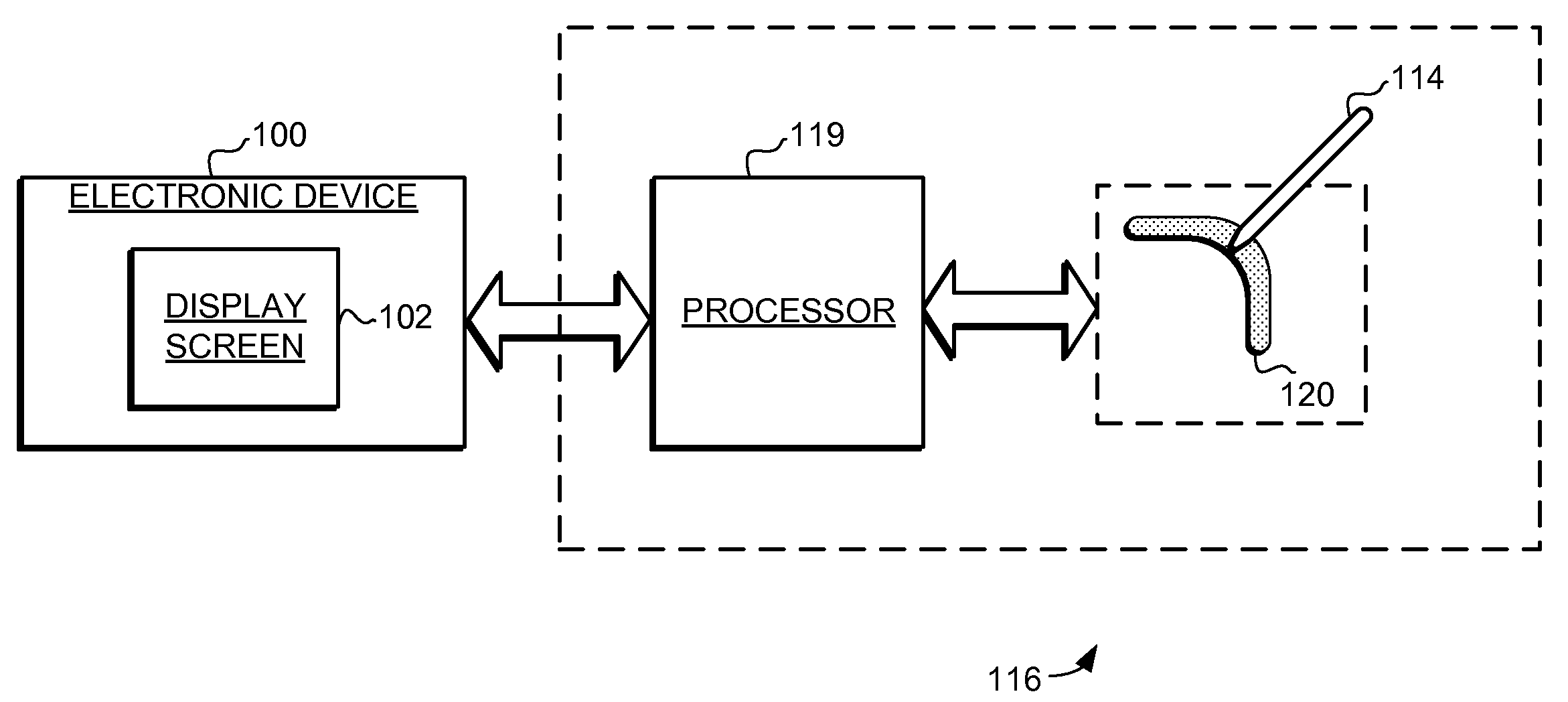
[0013]The embodiments of the present invention provide a proximity sensor device and method that facilitates orientation changes in displays. The proximity sensor device and method provide a user with the ability to indicate an orientation change in a display using the sensing region of a proximity sensor device as a user interface. In one specific embodiment, proximity sensor device is implemented to indicate an orientation change in a first way (e.g., clockwise) responsive to detected object motion along the sensing region in a first direction, and is further implemented to indicate an orientation change in a second way (e.g., counter-cl...


PUM


Abstract

A proximity sensor device and method is provided that facilitates orientation changes in displays. The proximity sensor device and method provide a user with the ability to indicate an orientation change in a display using the sensing region of a proximity sensor device as a user interface. In one specific embodiment, proximity sensor device is implemented to indicate an orientation change in a first way responsive to detected object motion along the sensing region in a first direction, and is further implemented to indicate an orientation change in a second way responsive to detected object motion along the sensing region in a second direction. Thus, a user can cause orientation changes of different ways through the use of object motions in different directions along the sensing region.

Description

FIELD OF THE INVENTION[0001]This invention generally relates to electronic devices, and more specifically relates to proximity sensor devices and using a proximity sensor device for producing orientation changes on display screens of electronic devices.BACKGROUND OF THE INVENTION[0002]Proximity sensor devices (also commonly called touch pads or touch sensor devices) are widely used in a variety of electronic systems. A proximity sensor device typically includes a 2D or 3D sensing region, often demarked by a 2D surface, which uses capacitive, resistive, inductive, optical, acoustic and / or other technology to determine the presence, location and / or motion of one or more fingers, styli, and / or other objects. The proximity sensor device, together with one or more finger(s) and / or other object(s), can be used to provide an input to the electronic system. For example, proximity sensor devices are used as input devices for larger computing systems, such as those found integral within noteb...

Claims


Application Information

Patent Timeline
Patent Type & Authority Applications(United States)
IPC IPC(8): G06F3/041
CPCG06F1/1626G06F1/1643G06F1/1684G06F1/169G06F2200/1614G06F2200/1637
Inventor HOVDEN, TORBJORNHUIE, MARK ANDREWLE, THUY THANH BICHACKER, JR., PHILLIP FRANK
Owner WACOM CO LTD
Why Eureka
Try Eureka