Image display apparatus and method, and image generating apparatus and method

Inactive Publication Date: 2008-11-20
MITSUBISHI ELECTRIC CORP
View PDF3 Cites 45 Cited by
  • Summary
  • Abstract
  • Description
  • Claims
  • Application Information

AI Technical Summary

Benefits of technology

[0009]An object of the present invention is to reduce motion blur without increasing the amount of pixel data that must be transferred to the display device.
[0013]Although the resampling process greatly reduces the rate at which pixel data must be sent to the image display unit, the image display unit displays each pixel in each subframe at its correct spatial and temporal position. The image display unit can therefore reproduce the spatial definition of still images in the received image signal, and can also display moving images that are perceived without motion blur.

Problems solved by technology

With the advent of high-definition television broadcasting and vastly increased computer processing speeds, the number of pixels displayed in an image is rapidly rising, requiring display devices with denser pixel arrays, but manufacturing these display devices is an exacting process, attended by high costs and reduced manufacturing yields.
A problem with display devices of both the hold type and the pulse-width modulation type is that moving video images are blurred by a discrepancy between display position and the position tracked by the viewer's eye as it attempts to follow the motion.
A problem with these devices, however, is that they require pixel data to be read out and transferred at an increased rate.
Both the display device and the electronics that control it must therefore operate at an increased speed, which is difficult to accomplish at a low cost.

Method used


Image

  • Image display apparatus and method, and image generating apparatus and method
  • Image display apparatus and method, and image generating apparatus and method
  • Image display apparatus and method, and image generating apparatus and method

Examples


first embodiment

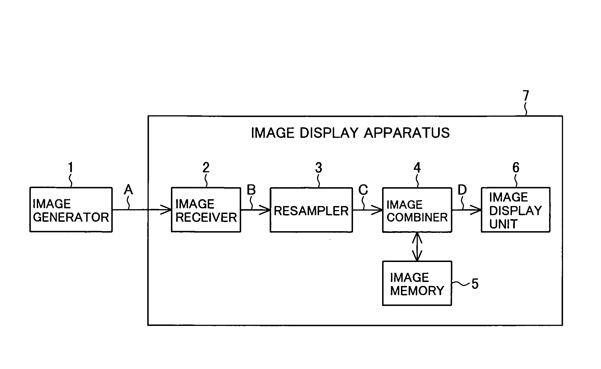
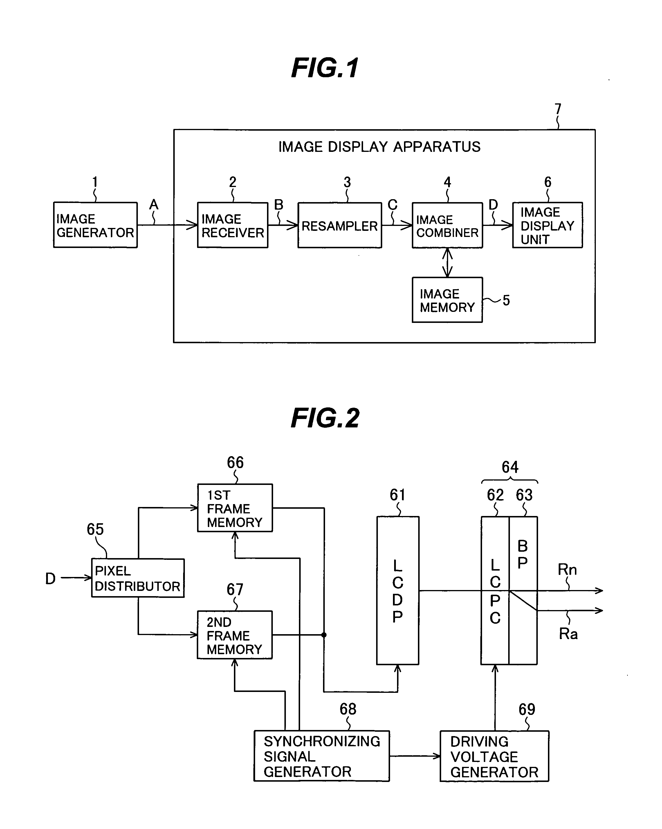
[0039]Referring to FIG. 1, in the first embodiment, an image signal A generated by an image generator 1 is received by an image receiver 2 and output from the image receiver 2 as a sampled digital image signal B. A resampler 3 resamples image signal B and outputs a resampled image signal C. An image combiner 4 stores resampled images in an image memory 5, and combines them to generate a combined image signal D. An image display unit 6 displays the combined image signal D as a plurality of subframes. The image receiver 2, resampler 3, image combiner 4, image memory 5, and image display unit 6 constitute an image display apparatus 7 embodying the present invention.

[0040]The image signal A may be an electrical signal carried on a cable linking the image generator 1 to the image display apparatus 7, or a wireless signal such as a broadcast television signal or an optical signal. If image signal A is an analog signal, the image receiver 2 samples image signal A and performs analog-to-dig...

second embodiment

[0088]Instead of reducing the data transfer rate, the second embodiment interpolates frames to reduce motion blur without raising the data transfer rate.

[0089]Referring to FIG. 13, the second embodiment employs an image generator 1, image receiver 2, resampler 3, image memory 5, and image display unit 6 as in the first embodiment, but adds an interpolated image generator 10 and has a different image combiner 11. The image receiver 2, resampler 3, image memory 5, image display unit 6, interpolated image generator 10, and image combiner 11 form an image display apparatus 12.

[0090]The image signal A generated by the image generator 1 is input to the image receiver 2 and converted or reformatted to create a digital image signal B, which is supplied to the resampler 3 and the interpolated image generator 10. The resampler 3 samples each frame of image signal B with a predetermined sampling phase to generate the resampled image signal C, which is supplied to the image combiner 11.

[0091]Th...

third embodiment

[0107]The third embodiment of the invention is an image generating apparatus that generates an image signal that can be displayed by a pixel-shifting image display device to produce high-definition blur-free images without requiring a high data transfer rate.

[0108]Referring to FIG. 17, in the third embodiment, an image generator 1 outputs a sampled digital image signal A directly to a resampler 3, which resamples the image signal and outputs a resampled image signal C to an image combiner 4. Using an image memory 5, the image combiner 4 outputs a combined image signal D to an image transmitter 13, which sends the combined image as an output image signal F to an image display unit 6. The image generator 1, resampler 3, image combiner 4, image memory 5, and image transmitter 13 constitute the image generating apparatus 14. The image signal F supplied from the image nerating apparatus 14 to the image display unit 6 may be an electrical signal carried on a cable, or a wireless signal, o...


PUM


Abstract

An image signal representing consecutive video frames is resampled, using different sampling phases so that different subsets of pixels are taken from each frame in a consecutive set of frames. The resulting set of resampled frames is combined into a single frame and transferred to an image display unit that divides the single frame into subframes and displays the subframes sequentially with different pixel shifts. Each pixel in each subframe is displayed at its correct spatial and temporal position. Although the resampling process greatly reduces the pixel data transfer rate, the image display unit can reproduce still images without loss of definition and moving images without motion blur.

Description

BACKGROUND OF THE INVENTION[0001]1. Field of the Invention[0002]The present invention relates to an image display apparatus and method, and an image generating apparatus and method.[0003]2. Description of the Related Art[0004]Display devices that modulate a discrete matrix of picture elements or pixels, such as liquid crystal, plasma, and electroluminescent (EL) or organic light-emitting diode (O-LED) panels and digital micromirror devices (DMDs), are employed in a variety of image display apparatus, including flat-panel television sets, projection television sets, projectors, and computer monitors.[0005]With the advent of high-definition television broadcasting and vastly increased computer processing speeds, the number of pixels displayed in an image is rapidly rising, requiring display devices with denser pixel arrays, but manufacturing these display devices is an exacting process, attended by high costs and reduced manufacturing yields. Manufacturers have accordingly devised dis...

Claims


Application Information

Patent Timeline
IPC IPC(8): G06F3/038
CPCG09G3/001G09G3/007G09G2320/0261
Inventor SOMEYA, JUNNAGASE, AKIHIROSUZUKI, YOSHITERUOKUMURA, AKIRA
Owner MITSUBISHI ELECTRIC CORP
Why Eureka
Try Eureka