Liquid droplet jetting apparatus

a technology of liquid droplets and jetting apparatuses, which is applied in the direction of printing, other printing apparatus, etc., can solve the problems of destabilizing the jetting operation, contaminating the inside of the apparatus, and affecting the jetting operation, so as to reduce contamination, save energy, and recover the mist efficiently

Active Publication Date: 2008-11-20
BROTHER KOGYO KK
View PDF11 Cites 6 Cited by
  • Summary
  • Abstract
  • Description
  • Claims
  • Application Information

AI Technical Summary

Benefits of technology

[0025]According to the liquid droplet jetting apparatus of the present invention, since the suction port opens in the vicinity of the nozzle, it is possible to suck the mist, which is generated when the liquid droplets are jetted from the nozzle, together with the air around the nozzle. Therefore, it is possible to reduce a contamination due to adhering of the mist at the interior of the apparatus.
[0026]In the liquid droplet jetting apparatus of the present invention, the suction port may be continuously open around the nozzle. In this case, it is possible to suck efficiently the mist, which is generated when the liquid droplets are jetted from the nozzle, together with the air around the nozzle.
[0027]In the liquid droplet jetting apparatus of the present invention, the nozzle may be formed as a plurality of nozzles arranged in an orthogonal direction orthogonal to the predetermined direction; the plurality of nozzles may form a nozzle row; and the suction port may be formed to extend in the orthogonal direction, with respect to the nozzle row, on both sides of the predetermined direction, and the suction port may be formed as a plurality of suction ports arranged in the orthogonal direction, with respect to the nozzle row, on both sides of the predetermined direction. When the jetting head unit jets the liquid droplets while moving in a predetermined direction, the mist tends to flow toward a side opposite to the movement direction of the jetting head unit due to an air flow which is generated by the movement of the jetting head unit. According to the liquid droplet jetting apparatus of the present invention, since the suction port opens on both sides of the movement direction of the jetting head unit with respect to the nozzle row, it is possible to recover the mist efficiently.

Problems solved by technology

In a liquid droplet jetting apparatus such as an ink-jet recording apparatus, if there is a portion which generates heat at the time of jetting a liquid, the generated heat affects and destabilizes the jetting operation.
Moreover, in liquid droplet jetting apparatuses, it has hitherto been known that fine liquid droplets (mist) are generated at the time of jetting liquid droplets from a nozzle, and these fine liquid droplets contaminate an inside of the apparatus.
The heat of the circuit element is transferred to the jetting head, and there is a possibility that the jetting operation is destabilized.

Method used


Image

  • Liquid droplet jetting apparatus
  • Liquid droplet jetting apparatus
  • Liquid droplet jetting apparatus

Examples


Embodiment Construction

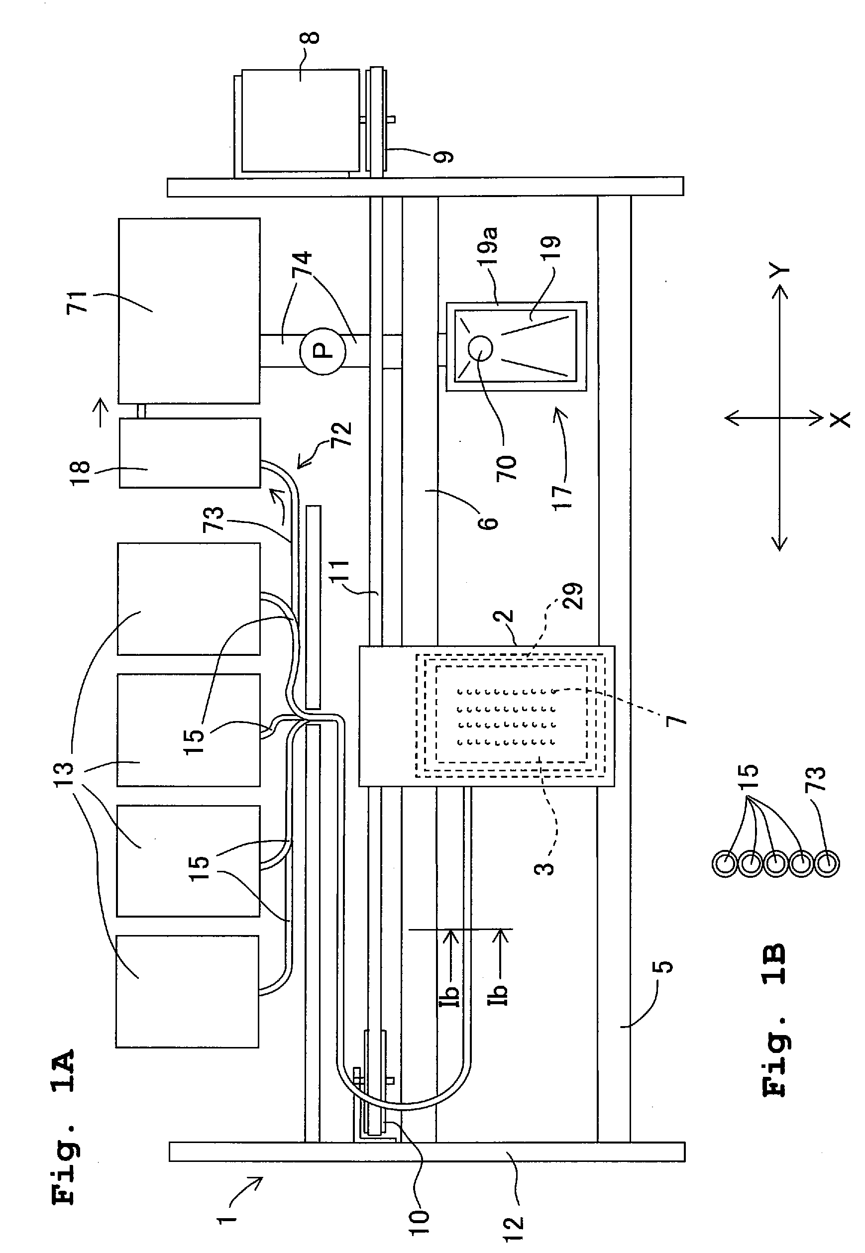
[0036]Basic embodiments of the present invention will be described below. FIG. 1A is a schematic plan view of a recording apparatus 1 as a liquid droplet jetting apparatus of the present invention. The recording apparatus 1 may be applied to an independent printer apparatus or may also be applied to a printer function (recording section) of a multi-function apparatus which is provided with a plurality of functions such as a facsimile function and a copy function.

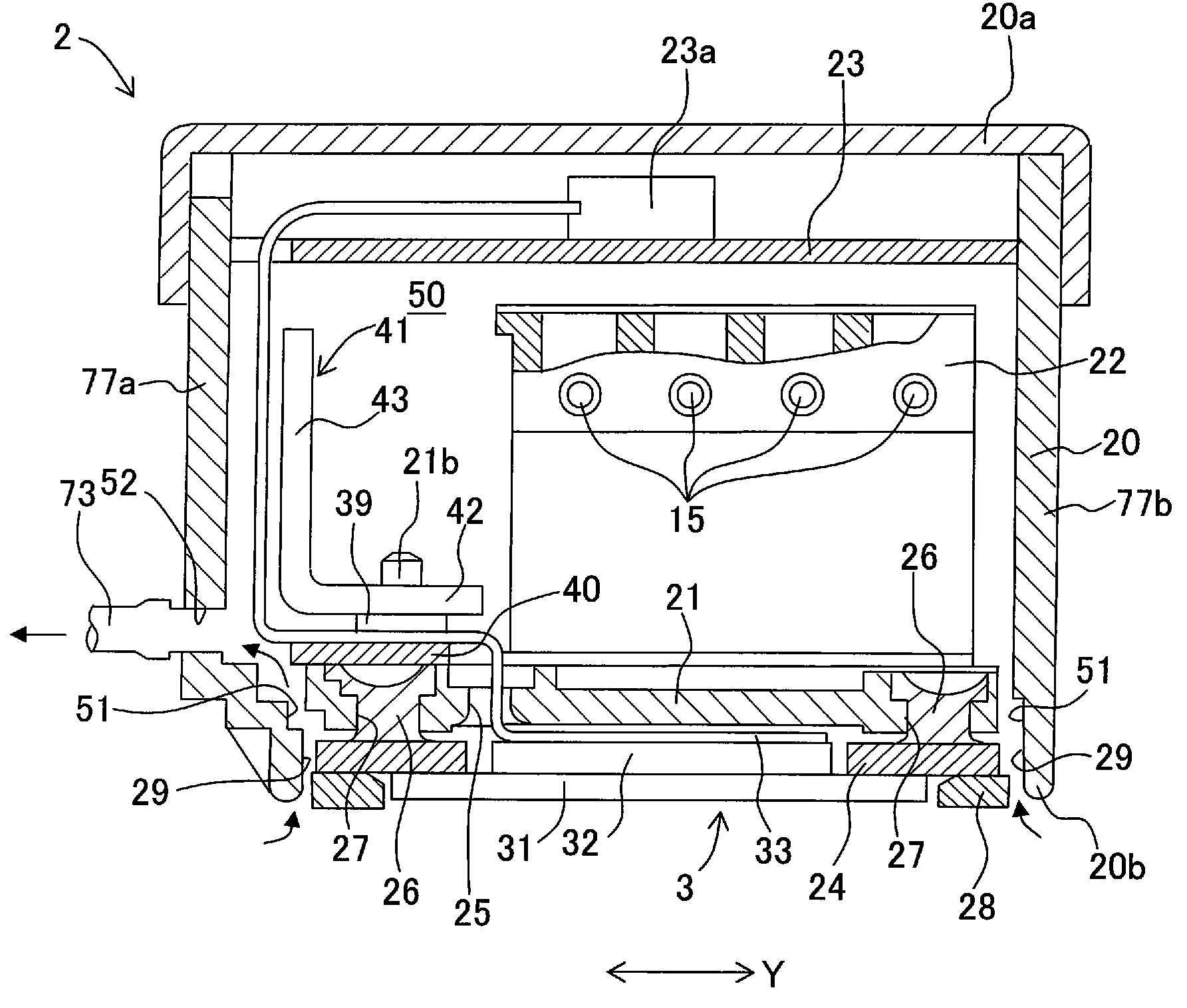
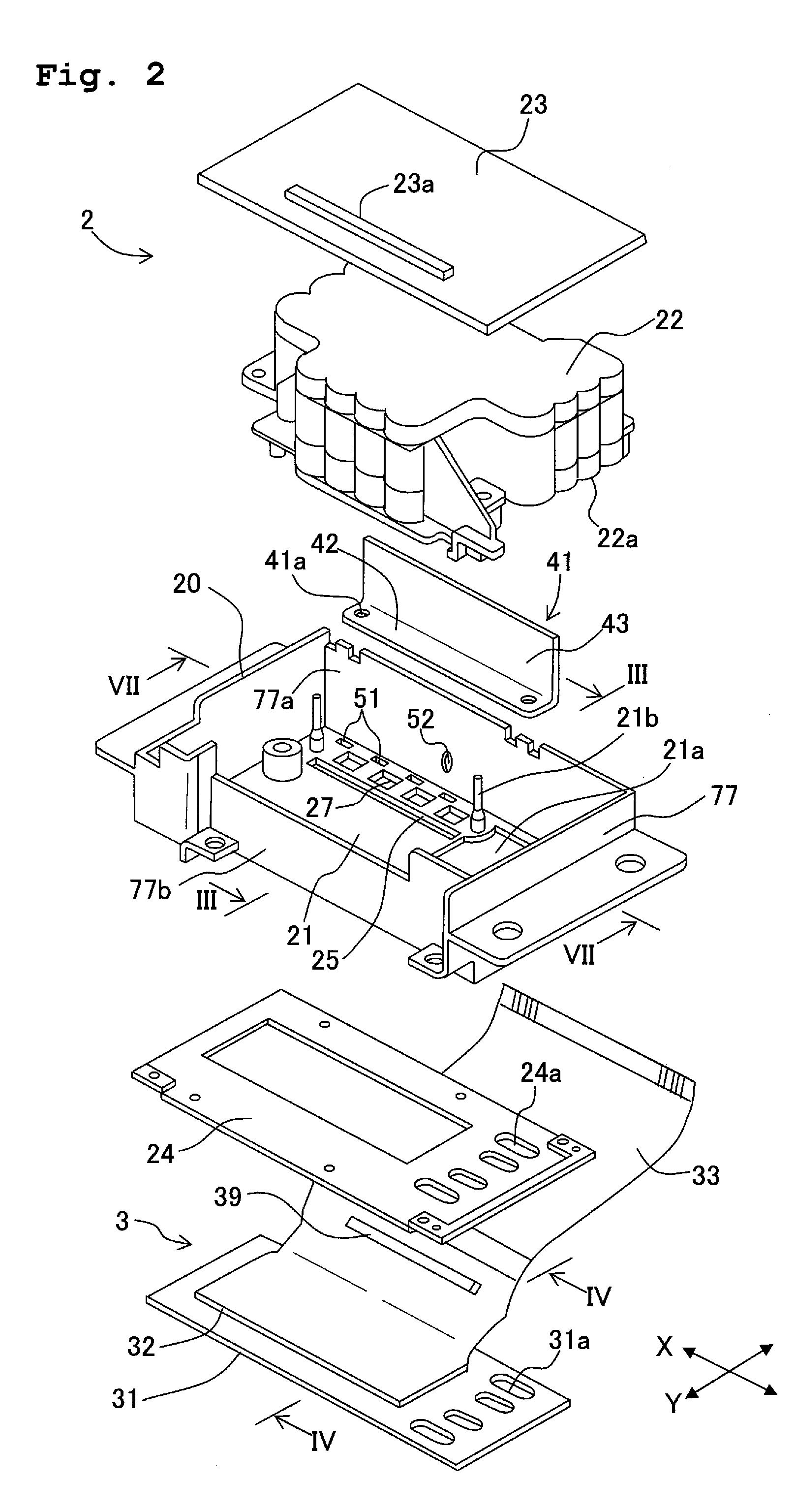
[0037]The recording apparatus 1, as shown in FIG. 1A, is provided with a jetting head unit 2 which forms a carriage. A jetting head 3 is mounted on the jetting head unit 2, with nozzles 7 of the jetting head 3 exposed on a lower surface of the jetting head unit 2. A first guide member 5 and a second guide member 6 are members which movably support the jetting head unit 2 which is the carriage, to be movable in a main scanning direction (Y-axis direction). The jetting head unit 2 reciprocates along the Y-axis direction by a d...


PUM


Abstract

A liquid droplet jetting apparatus includes a jetting head unit which has a nozzle which jets droplets of a liquid, and a heat generating section, a suction port which is formed in the jetting head unit, and which opens near the nozzle, and a suction device which sucks air around the nozzle from the suction port, and cools down the heat generating section of the jetting head unit by the air which is sucked. Since the heat generating portion is cooled down by the air sucked from the suction port by the suction device, it is possible to reduce a possibility of the heat of the heat generating section being transferred to the jetting head unit, and destabilizing an operation of the jetting head unit. Moreover, since the suction port opens near the nozzle, it is possible to suck fine liquid droplets together with air around the nozzle.

Description

CROSS REFERENCE TO RELATED APPLICATION[0001]The present application claims priority from Japanese Patent Application No. 2007-128394, filed on May 14, 2007, the disclosure of which is incorporated herein by reference in its entirety.BACKGROUND OF THE INVENTION[0002]1. Field of the Invention[0003]The present invention relates to a liquid droplet jetting apparatus which includes a jetting head unit for jetting liquid droplets, and particularly to a cooling structure of a heat generating section of the liquid droplet jetting apparatus, and a structure which eliminates floating of fine liquid droplets (mist) which are generated when the liquid droplets are jetted from a nozzle.[0004]2. Description of the Related Art[0005]In a liquid droplet jetting apparatus such as an ink-jet recording apparatus, if there is a portion which generates heat at the time of jetting a liquid, the generated heat affects and destabilizes the jetting operation. Therefore, in U.S. Pat. No. 7,188,922 (correspond...

Claims


Application Information

Patent Timeline
Patent Type & Authority Applications(United States)
IPC IPC(8): B41J2/165
CPCB41J2/16523B41J29/377
Inventor KUBO, TOMOYUKI
Owner BROTHER KOGYO KK
Why Eureka
Try Eureka