Node, communication method, and program for node

Active Publication Date: 2008-11-20
NEC CORP
View PDF1 Cites 159 Cited by
  • Summary
  • Abstract
  • Description
  • Claims
  • Application Information

AI Technical Summary

Benefits of technology

[0108]The invention has been made in an effort to solve the above problems, and an object of the invention is to provide a node, a communication method, and a program for

Problems solved by technology

The term “broadcast storm” means a state in which the communication band of a network is overwhelmed due to continuous transfer of broadcast frames between the Ethernet switches connected to each other by a plurality of links, which results in unstable communication conditions over the entire network.
However, when the node 200 is out of order, it is impos

Method used


Image

  • Node, communication method, and program for node
  • Node, communication method, and program for node
  • Node, communication method, and program for node

Examples


first exemplary embodiment

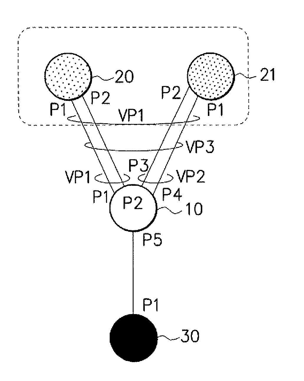
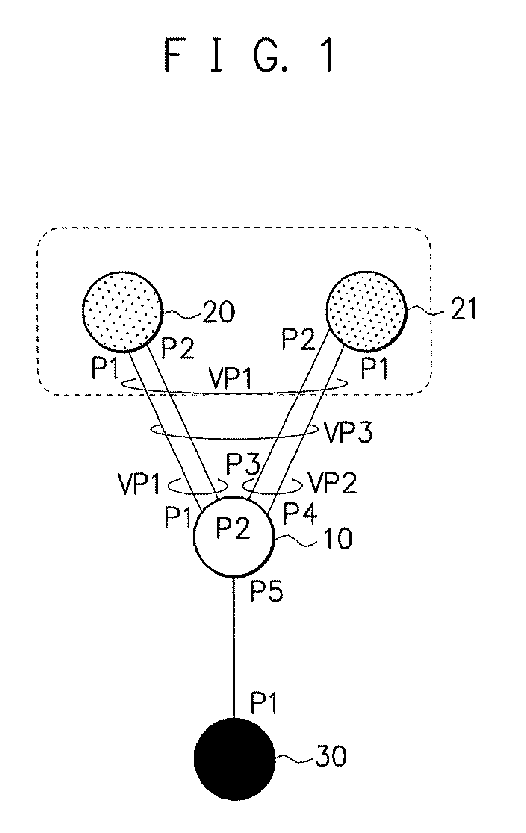
[0146]FIG. 1 is a diagram illustrating an example of the configuration of a network including a node according to a first exemplary embodiment of the invention. A node 10 according to the invention is connected to other nodes 20, 21, and 30. The nodes 20 and 21 are redundantly configured. A port P5 of the node 10 is connected to a port P1 of the node 30 by one physical link. A port P1 of the node 10 is connected to a port P1 of the node 20 by one physical link, and a port P2 of the node 10 is connected to a port P2 of the node 20 by one physical link. In addition, a port P3 of the node 10 is connected to a port P2 of the node 21 by one physical link, and a port P4 of the node 10 is connected to a port P1 of the node 21 by one physical link.

[0147]In the configuration of the network shown in FIG. 1, a LAG group (or virtual port) is set in the node 10 according to the invention as follows. The ports P1 and P2 of the node 10 according to the invention are registered in the same LAG grou...

second exemplary embodiment

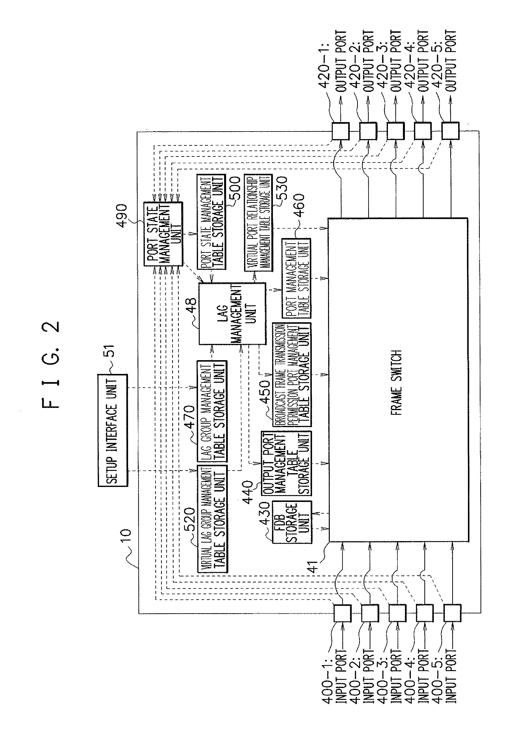
[0259]Next, a second exemplary embodiment of the invention will be described. In the second exemplary embodiment of the invention, a node 10 is also included in the configuration of the network shown in FIG. 1. In the node according to the first exemplary embodiment shown in FIG. 2, the port identifiers of the physical ports or the port identifiers of the virtual ports (that is, the virtual ports each of which is a group of a plurality of physical ports) allocated to the LAG groups are registered in the output information field of the FDB 431 (see FIG. 3). In contrast, in the node according to the second exemplary embodiment, the port identifiers of physical ports, the port identifier of virtual ports allocated to LAG groups, and the port identifier of a virtual port (that is, a virtual port, which is a group of a plurality of virtual ports) allocated to a virtual LAG group are registered in the output information field of the FDB 431.

[0260]In the following description, the port ide...


PUM


Abstract

The present invention provides a node capable of preventing the problems caused by switching between traffic communication paths when a link failure occurs. According to an embodiment of the invention, among ports of a node 10, ports P1 and P2 connected to a link between the node 10 and a node 20 are registered in a virtual port VP1, and ports P3 and P4 connected to a link between the node 10 and the node 30 are registered in a virtual port VP2. The virtual ports VP1 and VP2 are registered in a virtual port VP3 allocated to a virtual LAG group. When one link between the node 10 and the node 20 is disconnected, the node 10 transmits frames, which have been transmitted from a physical port connected to the link, from the virtual port including the physical port, among the virtual ports belonging to the virtual port VP3 allocated to the virtual LAG group.

Description

[0001]This application is based upon and claims the benefit of priority from Japanese paten application No. 2007-131854, filed on May 17, 2007, the disclosure of which is incorporated herein in its entirety by reference.BACKGROUND OF THE INVENTION[0002]1. Field of the Invention[0003]The present invention relates to a node, a communication method, and a program for a node, and more particularly, to a node, a communication method, and a program for a node capable of improving the reliability of communication.[0004]2. Description of the Related Art[0005]A backbone network that transfers a large amount of data traffic requires high reliability capable of preventing the interruption of communication even though a link between network nodes (hereinafter, simply referred to as nodes) is disconnected or the node is out of order. In order to meet the requirements, the following techniques have been developed: a link redundancy technique for virtualizing a plurality of links to one link; and ...

Claims


Application Information

Patent Timeline
IPC IPC(8): H04L12/56H04L45/24H04L45/16H04L45/243H04L45/586H04L47/41
CPCH04L45/00H04L45/245H04L45/28H04L49/351H04L49/357H04L49/552H04L49/70Y02B60/33Y02D30/50
Inventor OGASAHARA, DAISAKU
Owner NEC CORP
Why Eureka
Try Eureka