Marker arrangement information measuring apparatus and method

a technology of information measuring apparatus and marking arrangement, which is applied in the direction of instruments, image analysis, image enhancement, etc., can solve the problems of no method of enabling an observer to confirm information regarding

Active Publication Date: 2008-11-20
CANON KK
View PDF3 Cites 102 Cited by
  • Summary
  • Abstract
  • Description
  • Claims
  • Application Information

AI Technical Summary

Benefits of technology

[0019]In view of the above-described state of the art, when a marker image is captured by an image pickup apparatus to measure the position and the posture of each marker, the present invention gives an operator information regarding how many times the marke...

Problems solved by technology

The problem of registration in the AR technology is equivalent to, in the video see-through type, a problem of precisely determining the position and the posture of the image pickup apparatus in a scene (i.e., in a reference coordinate system defined in the scene).
Also, the problem of registration in the AR technology is equivalent to, in the optical see-through type, a problem of precisely determining the viewpoint of the observer or the position and the posture of the display in a scene.
Although the position and the posture of the marker can be measured by hand work using a tape measure and a protractor or a measuring instrument, the measurem...

Method used


Image

  • Marker arrangement information measuring apparatus and method
  • Marker arrangement information measuring apparatus and method
  • Marker arrangement information measuring apparatus and method

Examples


first exemplary embodiment

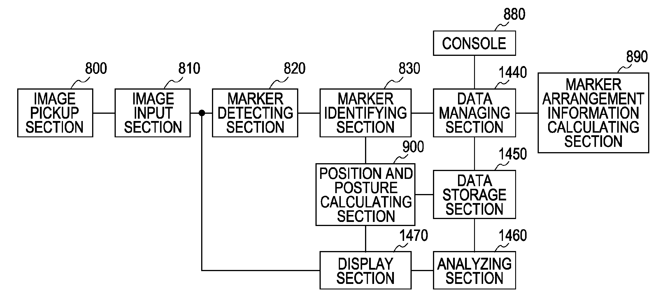
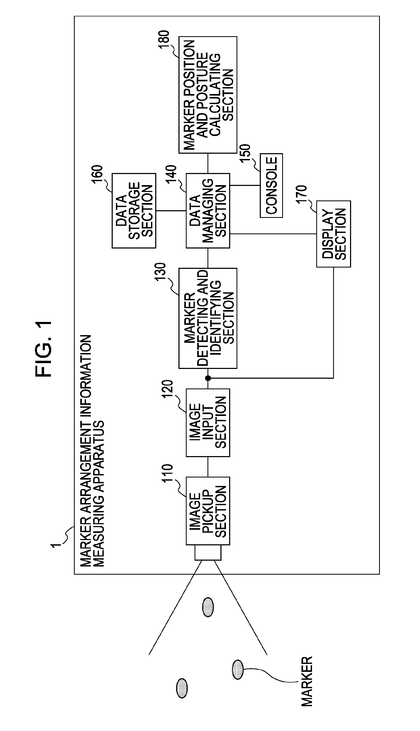
[0046]FIG. 1 is a block diagram showing the functional configuration of a marker arrangement information measuring apparatus 1 according to a first exemplary embodiment. An image pickup section 110 is constituted by a video camera and captures an image of a scene or an object on which markers are arranged. An image input section 120 takes the image captured by the image pickup section 110 into a computer. A marker detecting and identifying section 130 detects each marker from the image taken into the computer by the image input section 120 and identifies the detected marker. A data managing section 140 receives a marker detection result from the marker detecting and identifying section 130. When an instruction for acquiring the image captured by the image pickup section (apparatus) at the current time is input as a command entered through a console 150, the data managing section 140 stores, in a data storage section 160, the marker detection result input from the marker detecting an...

modification 1-1

[0069]While in the first exemplary embodiment the squares are drawn at the detected positions of the markers on the captured image in different colors depending on the number of times of the image capturing for each of the markers, the information regarding the number of times of the image capturing of the marker can also be notified to the user in any of other suitable manners. For example, only the outer frame portion of the square can be drawn in a different color instead of filling in the entire inner region of the maker with some color. Also, instead of changing the color, the marker for which the number of times of the image capturing is sufficient is drawn as a square at high transparency, while the marker for which the number of times of the image capturing is deficient is drawn as a square at low transparency. As an alternative, the transparency can be set to levels reversal to the above case. Further, the information regarding the number of times of the image capturing can...

modification 1-2

[0071]While in the first exemplary embodiment the information presenting method is changed depending on whether the image of the marker has been captured two or more times, the criterion number is not limited to two. The user can freely set the number of times of the image capturing, which serves as a criterion for changing the information presenting method, by using the console 150. In that case, the information presenting method is changed depending on the number of times of the image capturing, which is set as the criterion by the user.


PUM


Abstract

A marker arrangement information measuring apparatus includes an image acquiring unit configured to acquire a captured image, a marker detecting unit configured to detect markers from the captured image, a marker identifying unit configured to identify the marker detected by the marker detecting unit, an arrangement information calculating unit configured to calculate arrangement information of the marker based on an identification result of the marker identifying unit, an analyzing unit configured to analyze the identification result of the marker identifying unit, and a display unit configured to display an image corresponding to an analysis result of the analyzing unit on the captured image in a combined manner, thus presenting the analysis result to a user.

Description

BACKGROUND OF THE INVENTION[0001]1. Field of the Invention[0002]The present invention relates to processing to obtain arrangement information for each of markers arranged in a three-dimensional space.[0003]2. Description of the Related Art[0004]Recently, research of Mixed Realty (MR) technology has been developed. The MR technology is intended to merge a physical space and a virtual space, which is created by a computer, with each other without including seams. Of the MR technology, Augmented Reality (AR) technology for displaying the virtual space in a superimposed relation to the physical space has particularly received attention.[0005]There are two types of image display apparatus for use in the AR technology, i.e., the video see-through type and the optical see-through type. In the image display apparatus of the video see-through type, a combined image is displayed by drawing, on an image of a physical space captured by an image pickup apparatus, an image of a virtual space prod...

Claims


Application Information

Patent Timeline
IPC IPC(8): G06K9/66G06T7/60
CPCG06T7/0042G06T2207/30208G06T7/73
Inventor KOTAKE, DAISUKETAKEMOTO, KAZUKIMORITA, KENJIMAEDA, SONOKO
Owner CANON KK
Why Eureka
Try Eureka