System And Method For Identifying A Vascular Border

a system and border technology, applied in the field of vascular borders, can solve the problems of poor quality, time-consuming process, process is made more difficult,

Inactive Publication Date: 2008-11-20
THE CLEVELAND CLINIC FOUND
View PDF38 Cites 78 Cited by
  • Summary
  • Abstract
  • Description
  • Claims
  • Application Information

AI Technical Summary

Problems solved by technology

This is a very time consuming process.
Furthermore, this process is made more difficult when multiple images are being analyzed (e.g., to recreate a 3D vascular image, etc.) or the images are of poor quality (e.g., making the boundaries more difficult to see).

Method used


Image

  • System And Method For Identifying A Vascular Border
  • System And Method For Identifying A Vascular Border
  • System And Method For Identifying A Vascular Border

Examples


Embodiment Construction

[0022]The present invention provides a system and method of using a first vascular image, or more particularly a plurality of control points located thereon, to identify a border on a second vascular image. In the detailed description that follows, like element numerals are used to describe like elements illustrated in one or more figures.

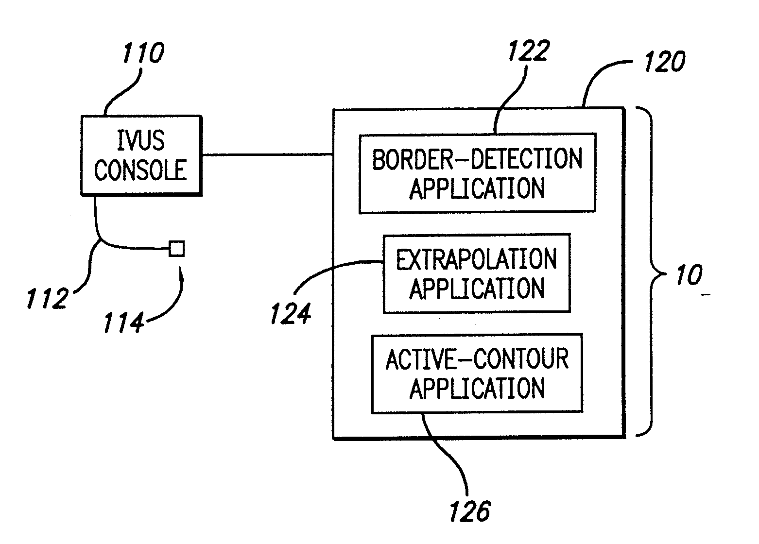
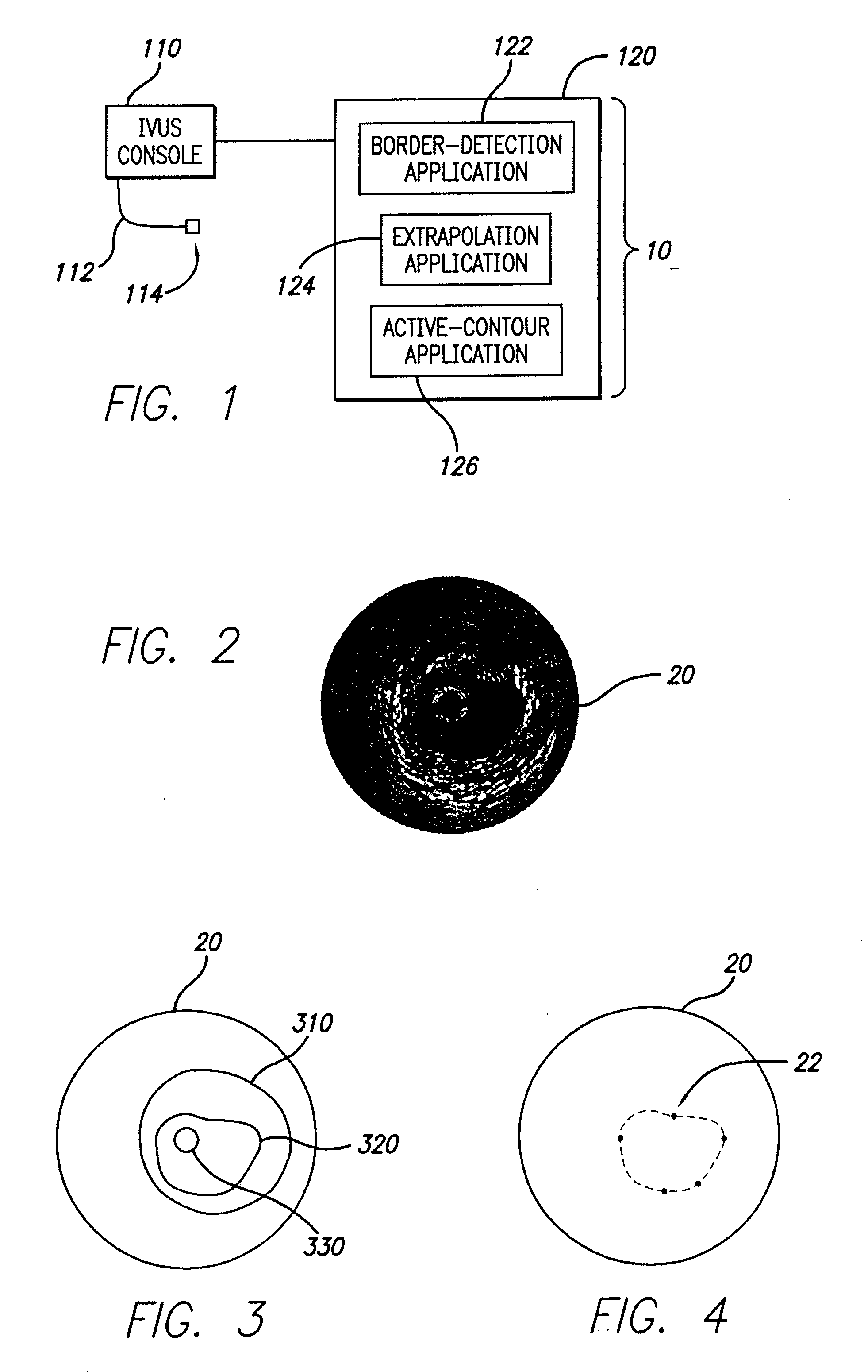
[0023]Embodiments of the present invention operate in accordance with an intra-vascular ultrasound (IVUS) device and a computing device electrically connected thereto. FIG. 1 illustrates a vascular-border-identification system 10 in accordance with one embodiment of the present invention. Specifically, an IVUS console 110 is electrically connected to a computing device 120 and a transducer 114 via a catheter 112. The transducer 114 is inserted into a blood vessel of a patient (not shown) and used to gather IVUS data (i.e., blood-vessel data, or data that can be used to identify the shape of a blood vessel, its density, its composition, etc.). The I...


PUM


Abstract

A system and method is provided for using a first vascular image, or more particularly a plurality of control points located thereon, to identify a border on a second vascular image. Embodiments of the present invention operate in accordance with an intra-vascular ultrasound (IVUS) device and a computing device electrically connected thereto. Specifically, in one embodiment of the present invention, an-IVUS console is electrically connected to a computing device and adapted to acquire IVUS data. The IVUS data (or multiple sets thereof) is then provided to (or acquired by) the computing device. In one embodiment of the present invention, the computing device includes a plurality of applications operating thereon—i.e., a border-detection application, an extrapolation application, and an active-contour application. These applications are used to (i) identify a border and control points on a first IVUS image (i.e., any IVUS image), (ii) extrapolate the control points to a second IVUS image (i.e., another IVUS image), (iii) identify a border on the second IVUS image, and (iv) adjust the border on the second IVUS image in accordance with at least one factor. In one embodiment of the present invention, the at least one factor is selected from a group consisting of gradient factor, continuity factor, and curvature factor.

Description

CROSS-REFERENCE TO RELATED APPLICATIONS[0001]This application claims the benefit pursuant to 35 U.S.C. § 119(e) of U.S. Provisional Patent Application Nos. 60 / 406,148, 60 / 406,183, 60 / 406,184, 60 / 406,185, 60 / 406,234, and 60 / 406,254, all of which were filed Aug. 26, 2002, and all are incorporated herein, in their entirety, by reference.BACKGROUND OF THE INVENTION[0002]1. Field of the Invention[0003]The present invention relates to vascular borders, or more particularly, to a system and method of using a first vascular image (or control points located therein) to identify a border on a second vascular image.[0004]2. Description of Related Art[0005]The present invention relates to medical imaging arts. It finds particular application to a system and method of, identifying a border in an intra-vascular ultrasound (IVUS) image. It should be appreciated that while the present invention is described in terms of identifying a luminal and medial-adventitial border on an IVUS image, the presen...

Claims


Application Information

Patent Timeline
Patent Type & Authority Applications(United States)
IPC IPC(8): A61B8/12G06T5/00G06T7/00
CPCA61B5/02007A61B8/12G06T7/0012G06T7/0083G06T2207/10132G06T2207/20101G06T2207/30101G06T7/12
Inventor KLINGENSMITH, JON D.VINCE, D. GEOFFREYNAIR, ANUJAKUBAN, BARRY D.
Owner THE CLEVELAND CLINIC FOUND
Why Eureka
Try Eureka