Dual stage cyclonic vacuum cleaner

a vacuum cleaner and cyclonic technology, applied in vacuum cleaners, cleaning filter means, vortex flow apparatus, etc., can solve the problems of increasing the overall height of the dust collector, increasing the overall width of the particle collector, etc., and achieves the effect of better and more advantageous overall results

Active Publication Date: 2008-11-27
TECHTRONIC FLOOR CARE TECH LTD
View PDF7 Cites 72 Cited by
  • Summary
  • Abstract
  • Description
  • Claims
  • Application Information

AI Technical Summary

Benefits of technology

[0007]Accordingly, the present disclosure provides an improved dual stage cyclonic air flow design which overcomes certain difficulties with the prior art designs while providing better and more advantageous overall results.

Problems solved by technology

One of the most common challenges regarding the design of a multi-stage cyclonic separator unit is the dust collector, which needs to be compact and easily serviceable by the user.
But, this can increase the overall height of the dust collector, which is especially disadvantageous for canister vacuum cleaners.
However, this can increase the overall width of the particle collector, which is especially disadvantageous for upright vacuum cleaners.
Also, with such a design, the diameter of the first particle collector remains relatively small, which is disadvantageous from the standpoint of separation efficiency.
However with such a design, the second cyclones are hidden and difficult to service due to lack of access.

Method used


Image

  • Dual stage cyclonic vacuum cleaner
  • Dual stage cyclonic vacuum cleaner
  • Dual stage cyclonic vacuum cleaner

Examples


second embodiment

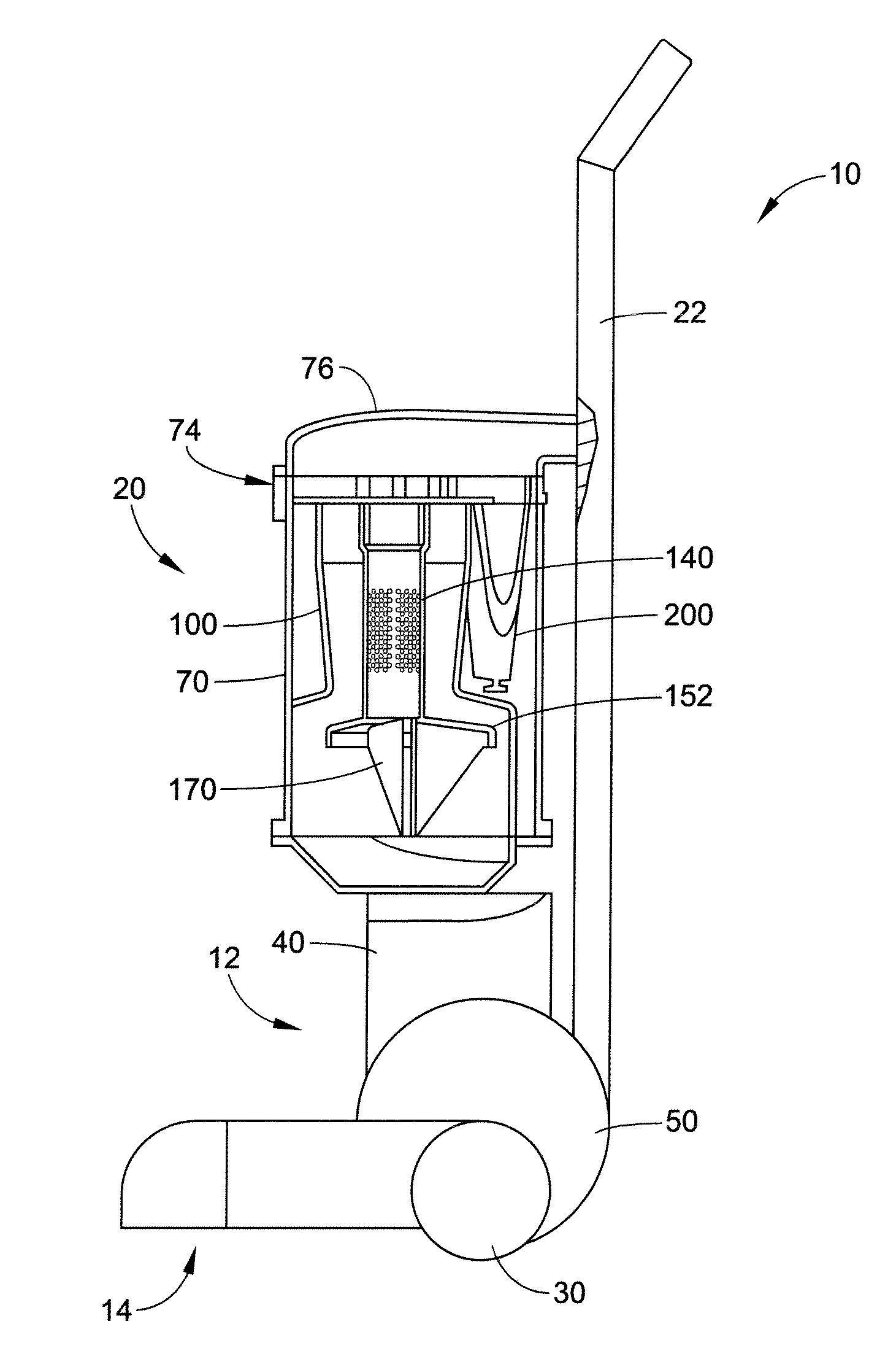
[0048]Connected to a lower, closed end 150 of the perforated tube 140 is a shroud 152 for retarding an upward flow of dirt and dust particles that have fallen below the lower end 108 of the first stage separator 100. Details of the perorated tube and shroud will be described below with respect to the dust collector.

[0049]A laminar flow member, such as one or more baffles or fins 170, is mounted to one of the shroud 152 and the closed lower end 150 of the perforated tube 140. At least a portion of the laminar flow member is encircled by the shroud 152. The laminar flow member extends partially into the first dust collection chamber 82 and is positioned centrally within the first dust collection chamber. As shown in FIG. 5, the depicted baffle 170 can be cruciform in shape and include a cross blade assembly, which can be formed of two flat blade pieces that are oriented approximately perpendicular to each other. It should be appreciated that the baffles 170 are not limited to the conf...

first embodiment

[0063]Similar to the first embodiment, the first and second dust collection chambers 340, 380, respectively, are configured to independently store and empty dirt and dust particles separated by the respective first and second cyclone parts 88′, 90′. Pivotally secured to a lower portion of the cyclone main body 320 is a first bottom plate or lid 382. As shown in FIGS. 8 and 13, the cyclone main body wall can include a sidewall opening 384 which allows for removal of the dirt particles collected in the second dust collection chamber 380. A drawer 390 can be removably received in the opening 384 for collecting separated dust particles. The drawer can include a handle or like means (not shown) for allowing a user to grip the drawer and remove the drawer so that dust collected in the second dust collection chamber can be emptied. A seal (not shown) can be fitted around the drawer 390 to create a seal between the drawer and wall 328. A conventional latch assembly can be used to maintain t...

third embodiment

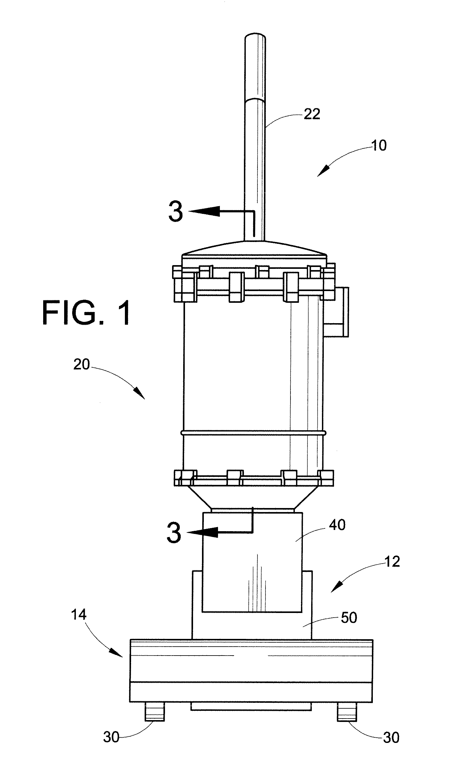
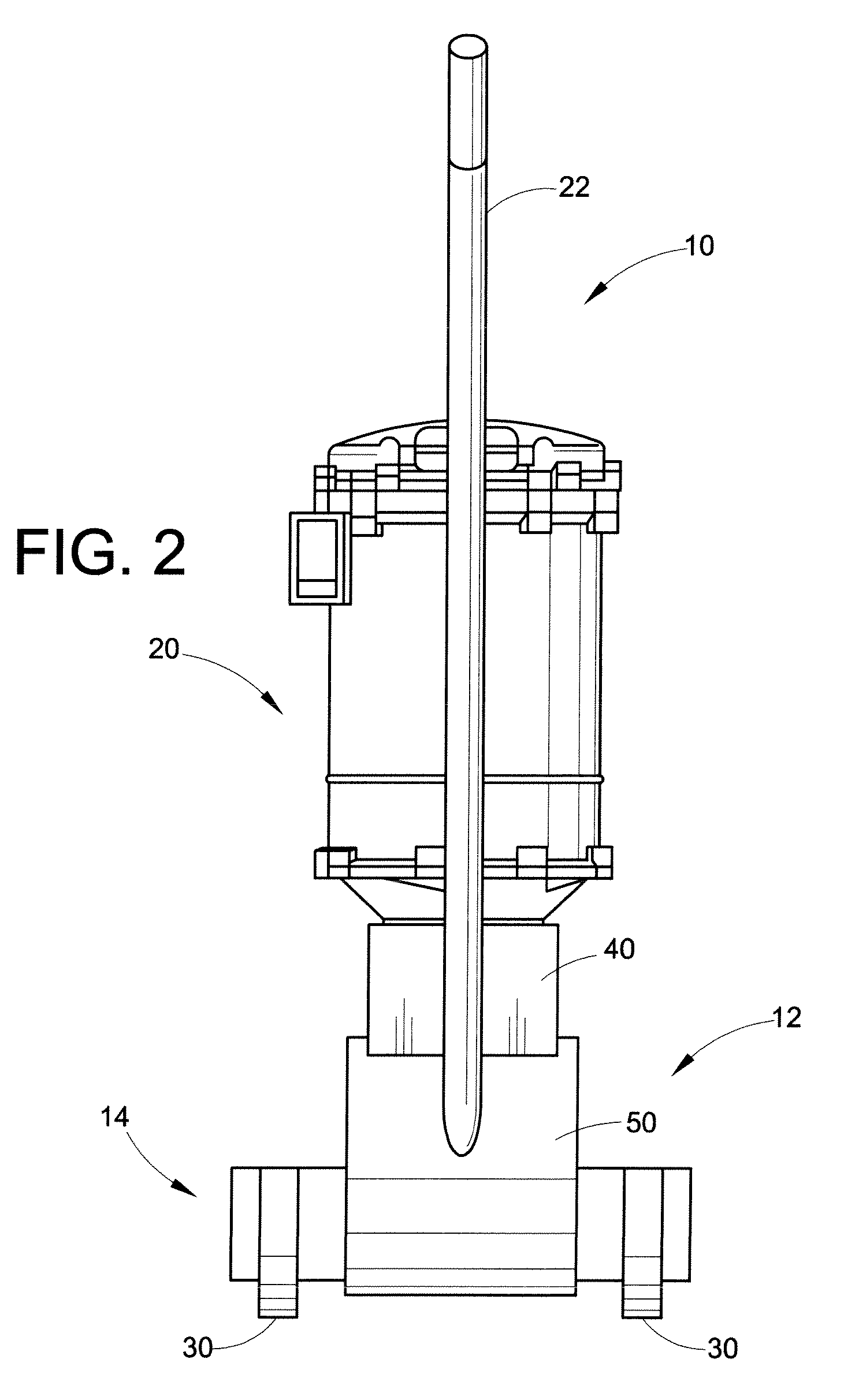
[0069]With reference now to FIGS. 14-17, a canister vacuum cleaner 500 utilizing a dust collector according to one of the aforementioned embodiments is illustrated. In the depicted embodiment, the dust collector is substantially similar to dust collector 20. Reference numerals with a double primed suffix (″) refer to like components (e.g., dust collector 20 is referred to by reference numeral 20″), and new numerals identify new components in this

[0070]With reference to FIGS. 14-17, the canister vacuum cleaner 500 generally includes a base member 502, an electric motor and fan assembly 504 and dust collector 20″ supported on the base member, and a hose and nozzle assembly (not shown), which is in fluid communication with the dust collector through a conduit 510 and hose fitting 512. The conduit directs dust-laden air tangentially into the dust collector. A latch assembly (not shown) can be mounted to the base member 502 for releasably securing the dust collector thereto. The base mem...


PUM

PropertyMeasurementUnit
acute angleaaaaaaaaaa
outer circumferenceaaaaaaaaaa
constant radiusaaaaaaaaaa

Abstract

A home cleaning appliance comprises a housing, an airstream suction source, a cyclone main body, and a dirt cup. The housing includes a main suction opening. The airstream suction source is mounted to the housing and includes a suction airstream inlet and a suction airstream outlet. The suction source selectively establishes and maintains a flow of air from the main suction opening, via the airstream inlet, to the airstream outlet. The cyclone main body is supported by the housing and is in communication with the main suction opening. The cyclone main body has a uniform outer circumference and includes a first stage separator, and a plurality of downstream second stage separators. The first stage separator has a longitudinal axis offset from a longitudinal axis of the cyclone main body in order to accommodate the second stage separators. The dirt cup is connected to the cyclone main body. The dirt cup includes a first particle collector and a second particle collector. The first particle collector communicates with the first stage separator for collecting dust particles from the first stage separator. The separate second particle collector communicates with the plurality of second stage separators for collecting dust particles from the second stage separators.

Description

CROSS REFERENCE TO RELATED APPLICATIONS[0001]This application claims priority from U.S. Provisional Patent Application Ser. No. 60 / 931,532 filed May 24, 2007, which provisional patent application is expressly incorporated herein by reference, in its entirety.BACKGROUND[0002]The present disclosure relates to vacuum cleaners. More particularly, the present disclosure relates to dual stage cyclonic vacuum cleaners used for suctioning dirt and debris from carpets and floors. Such vacuum cleaners can be upright, canister, hand-held or stationary, built into a house. Moreover, cyclonic designs have also been used on carpet extractors and “shop” type vacuum cleaners.[0003]Upright vacuum cleaners are well known in the art. The two major types of traditional vacuum cleaners are a soft bag vacuum cleaner and a hard shell vacuum cleaner. In the hard shell vacuum cleaner, a vacuum source generates the suction required to pull dirt from the carpet or floor being vacuumed through a suction openin...

Claims


Application Information

Patent Timeline
Patent Type & Authority Applications(United States)
IPC IPC(8): A47L9/10
CPCA47L9/1625A47L9/1641A47L9/1666A47L9/1683B01D45/12B04C5/185
Inventor MAKAROV, SERGEY V.SALO, ROBERT A.CIPOLLA, MARK E.KEGG, STEVEN W.
Owner TECHTRONIC FLOOR CARE TECH LTD
Why Eureka
Try Eureka