Gasket package

Active Publication Date: 2007-11-01
A LOK PROD +1
View PDF21 Cites 4 Cited by
  • Summary
  • Abstract
  • Description
  • Claims
  • Application Information

AI Technical Summary

Benefits of technology

[0006] Historically, the gasket and the clamp were shipped to the customer loose, either in a shared packaging or separately. For gaskets which have an end embedded into a cast member, it is common practice in the industry to take the gasket and mount it on hole forming equipment that positions the end to be embedded in the desired location during the casting of precast components in steel shaping molds. After the precast component is adequately cured, the precast producer will demold the component from the steel mold, remove the hole forming equipment and store the precast component. When it comes time to ship the precast component to the job site for installation, the manufacturer must locate and match the correct clamp to the gasket or make provisions for the contractor to do the same so that all gasket components are available at the time of installation. Such installations could be a short distance from the producer of the precast component, or as far as several hundred miles away. It is apparent that there can be much aggravation and expense associated with lost or misplaced clamps, not to mention the liability risk when the contractor goes to th

Problems solved by technology

It is apparent that there can be much aggravation and expense associated with lost or misplaced clamps, not to mention the liability risk when the contractor goes to the local hardware store to improvise

Method used


Image

  • Gasket package
  • Gasket package
  • Gasket package

Examples


first embodiment

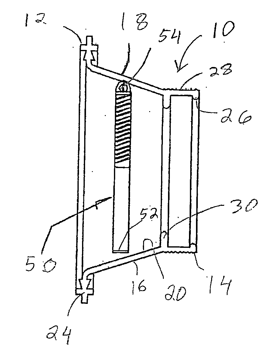
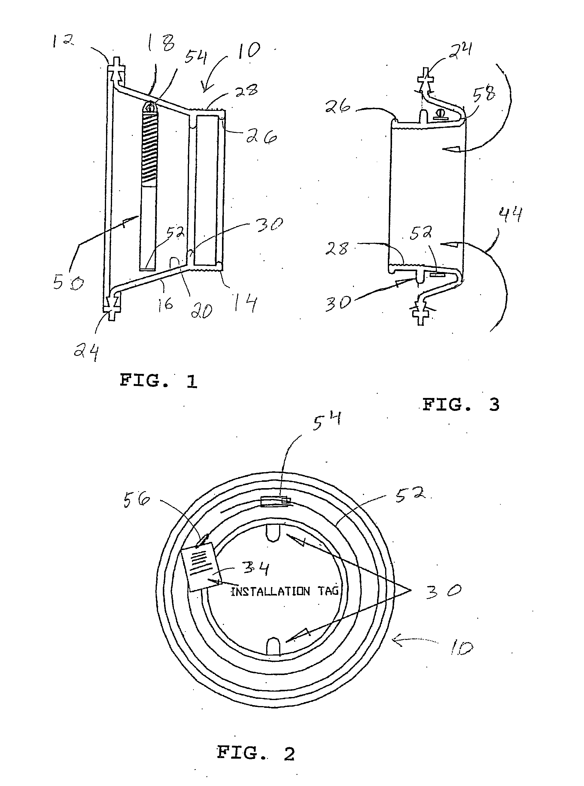
[0050] Referring now to the drawings, wherein the showings are for purposes of illustrating preferred embodiments of the invention only and not for purposes of limiting same, FIG. 1 illustrated a gasket assembly according to the present invention. In FIG. 1, a gasket body 10 is provided. The gasket body includes a first or mounting end 12 and a second or pipe engaging end 14. An intermediate portion 16 connects the two ends. As is evident from FIG. 1, the gasket body can have a somewhat tapered configuration. The gasket body also includes a first wall 18 and a second wall 20. The first and second walls 18 and 20 of the gasket can be either the inner wall or the outer wall of the gasket, depending on its orientation. An anchoring projection 24 can be located at the first end 12. The anchoring projection is also sometimes known as the embedment end of the gasket. Located adjacent the second end 14 is a bead 26. While the anchoring projections 24 are located on the first wall 18, it is...

third embodiment

[0058] Referring to FIG. 7, the present invention illustrates a gasket body 90 having tabs 92. In this embodiment also, three such tabs are employed, only two being visible. A clamp band 94 having a tightening screw 96 is located adjacent the tabs 92. This embodiment of the gasket body would be employed in situations where there may not necessarily be a pipe extending through the gasket. In other words, a blind gasket is illustrated. If a pipe is to extend through the gasket, and end wall 98 of the gasket would be removed.

fourth embodiment

[0059] With reference now to FIG. 8, a gasket assembly according to the present invention is there illustrated. In this embodiment, a gasket body 100 includes tabs 102. As better seen in FIG. 9, located adjacent the tabs is a clamp band 104. In this embodiment also, three such tabs 102 are employed, as shown in FIG. 11. The clamp band includes a tightening screw 106, better illustrated in FIG. 10. The tightening screw is held in a pocket 108 defined in the gasket body 100.

[0060]FIG. 12 shows, another embodiment of the present invention. In this embodiment, a gasket body 120 includes a different means for securing the gasket in a transport orientation. Such means comprises a strap 122, better illustrated in FIG. 13. Located adjacent the strap is a band 124 of a clamping assembly. A tightening screw 126 for the band is illustrated in FIG. 12. The tightening screw is held in a pocket 128. As is evident from FIG. 13, the strap includes an aperture 130. When the strap is folded over, a p...


PUM


Abstract

A gasket assembly includes a one-piece gasket that has a mounting end, for mounting in an opening of an associated enclosure body, and a pipe engaging end, for receiving an associated pipe. An intermediate section is located between the mounting end and the pipe engaging end. A clamp assembly is used on the pipe engaging end of the gasket. The clamp assembly is looped to assume an annular configuration. A retaining member, of one piece with the gasket, extends from a wall of the gasket, for retaining the clamp assembly to the gasket in a transport position.

Description

BACKGROUND [0001] The present invention relates to gaskets for use in providing a liquid tight seal between an opening in a side wall and a pipe. More particularly, the invention relates to a packaging arrangement for retaining a clamp assembly with the gasket during transport of the gasket, before it is installed. SUMMARY OF THE INVENTION [0002] Gaskets or connectors made of rubber, or similar resilient material, are typically utilized in sewage systems for providing a liquid tight seal between a pipe and an opening in a side wall of a cast member, such as, for example, a manhole assembly. [0003] There are two standard techniques for mounting a gasket within an opening in a cast member. First, one can embed an end of the gasket into a cast member during the casting operation. In this manner, the gasket is integrally joined to the cast member during the casting operation as the cast member is being formed, for example, at the factory. [0004] The other technique is to mount the gaske...

Claims


Application Information

Patent Timeline
IPC IPC(8): F16L17/06
CPCF16L5/10
Inventor WESTHOFF, JAMES A.KELLY, JAMES A.HANDAGO, CHRISTOPHER
Owner A LOK PROD
Why Eureka
Try Eureka