
Freestanding window treatment support

a freestanding, window treatment technology, applied in the direction of curtain shields, curtain suspension devices, curtains, etc., can solve the problems of not solving the problem at all, the type of window treatment support is not acceptable for historic or other high-value buildings, and the gap between the gaping screw hole and the window frame or wall is left, etc., to achieve the effect of simple operation

Inactive Publication Date: 2008-11-27
DOBBIE JANE
View PDF42 Cites 0 Cited by
  • Summary
  • Abstract
  • Description
  • Claims
  • Application Information

AI Technical Summary

Benefits of technology

[0007]It is an object of the present invention to provide for a window treatment support that does not required screwing hardware into a wall, is aesthetically pleasing, and is simple to operate.
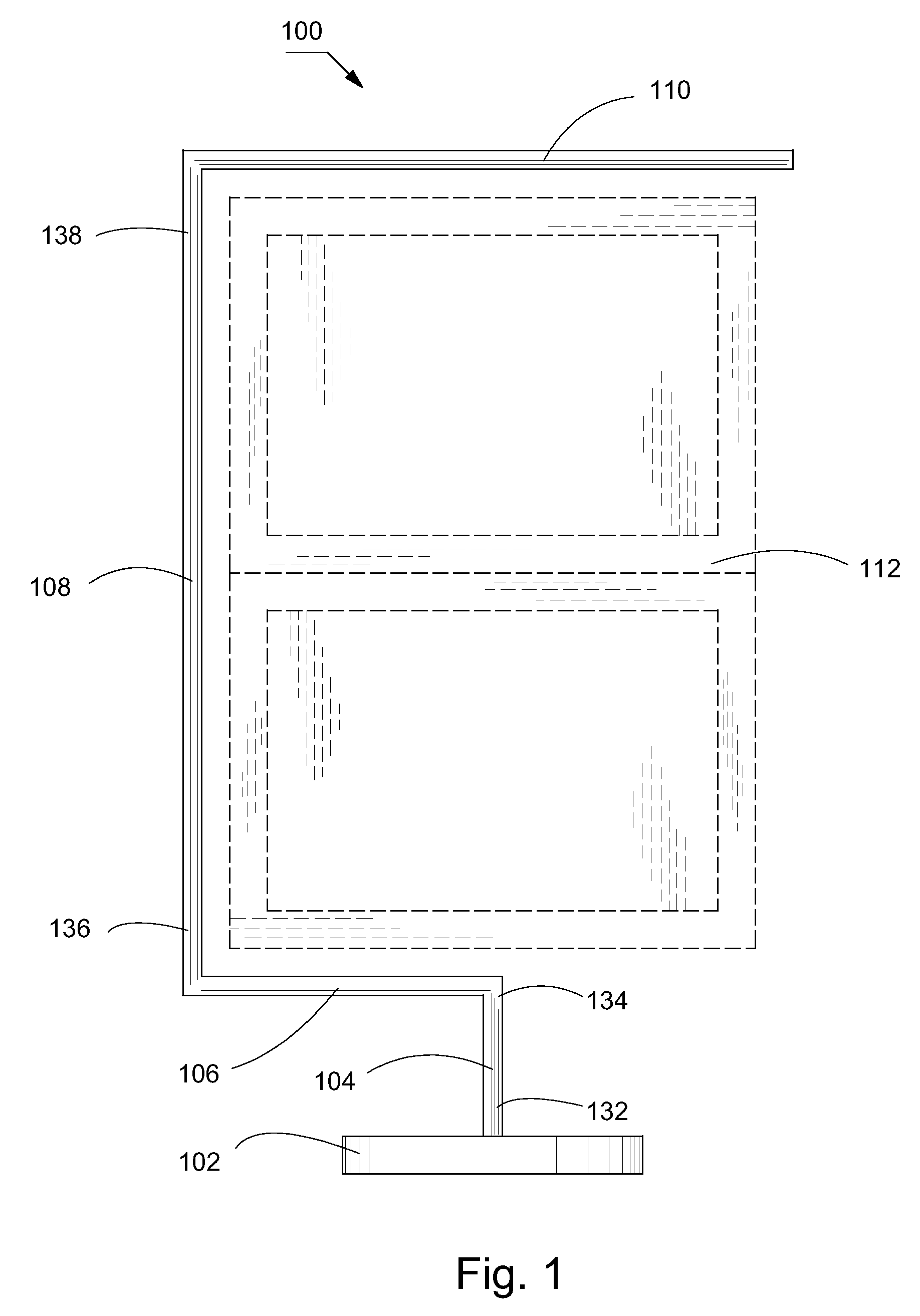
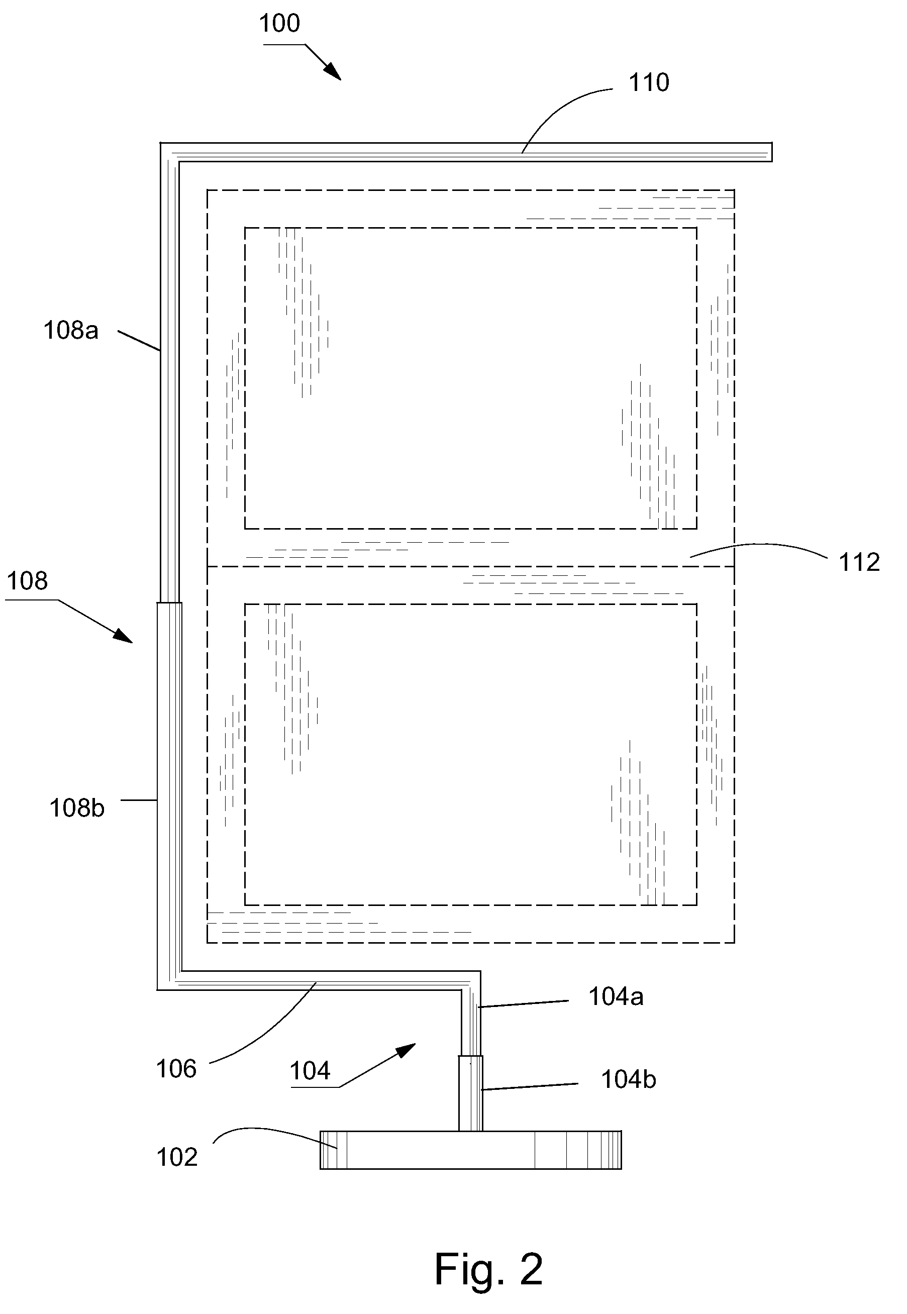
[0008]The present invention achieves these and other objectives by providing a freestanding window treatment support having a base, a lower vertical member connected to and extending from the base, an upper vertical member connected to the lower vertical member, and an upper horizontal member connected to the upper vertical member. The base has sufficient weight and footprint area for supporting a window treatment support and a window treatment. The lower vertical member has a first end and a second end, the first end being configured for connecting with the base so that the lower vertical member is preferably perpendicular to the base. The upper vertical member has a first end and a second end, the first end being configured for connecting with the lower vertical member second end. The upper horizontal member is configured for connecting adjacent the upper vertical member second end whereby a window treatment can be hung from the upper horizontal member over the top of a window. The upper vertical member can be taller than the window to which it is applied so that the support does not interfere with a view through the window. The lower vertical member is preferably shorter than the distance between the base and the bottom of the window, and the base is weighted and sized to prevent the support and window treatment from falling over.

Problems solved by technology

If a window treatment is changed in the future, gaping screw holes are left in the window frame or walls.
This type of window treatment support is not acceptable for historic or other high value buildings, where it is important not to damage the frame or walls.
However, the '305 patent has a means for securing the support assembly to the window frame using screws, which does not solve the problem at all.
Furthermore, it has two parts that must be operated simultaneously, and it is not aesthetically pleasing.

Method used


Image

  • Freestanding window treatment support
  • Freestanding window treatment support
  • Freestanding window treatment support

Examples


Embodiment Construction

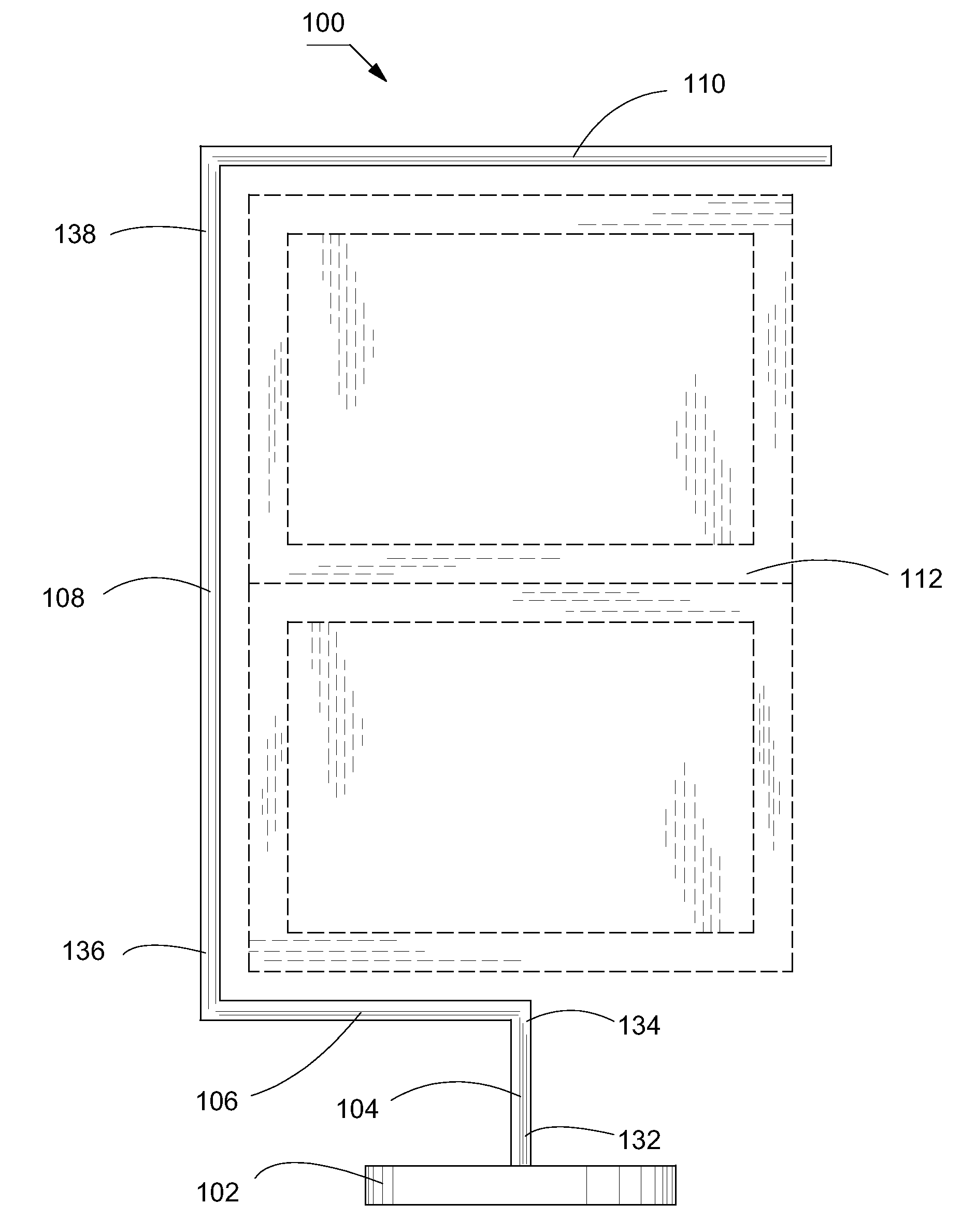
[0024]The preferred embodiment(s) of the present invention is illustrated in FIGS. 1-8. Turning to FIG. 1, a freestanding window treatment support 100 is supported by a base 102. The base 102 should have sufficient weight and footprint area to support the window treatment support 100 and a window treatment. A lower vertical member 104 is configured for connecting to the base 102 at a first end 132. The preferred features of the present invention are that it has only one base and one lower vertical member, which make it simple and aesthetically pleasing. It should be understood, however, that the window treatment support 100 of the present invention may be configured with several lower vertical members and bases to provide alternative and optional configurations below a window. The lower vertical member 104 has a second end 134 opposite the first end 132.

[0025]A lower horizontal member 106 is shown configured for connecting at one end with the lower vertical member 104. An upper vert...


PUM


Abstract

A freestanding window treatment support has a base, a lower vertical member having a lower vertical member first end and a lower vertical member second end, the lower vertical member first end connected to and extending vertically from the base, an upper vertical member having an upper vertical member first end and an upper vertical member second end, the upper vertical member first end connected to the lower vertical member second end, and an upper horizontal member connected adjacent the upper vertical member second end where the base has sufficient weight and footprint area for supporting a window treatment.

Description

BACKGROUND OF THE INVENTION[0001]1. Field of the Invention[0002]The present invention relates generally to window treatment devices having bases to support the device in an upright position.[0003]2. Description of the Prior Art[0004]Window treatments are interior decorations for a window or window frame, and include draperies, curtains, and valences. Window treatment supports are typically secured in place by drilling into surrounding walls or window frames and inserting screws. If a window treatment is changed in the future, gaping screw holes are left in the window frame or walls.[0005]This type of window treatment support is not acceptable for historic or other high value buildings, where it is important not to damage the frame or walls. One example that appears to address the problem is disclosed in U.S. Pat. No. 7,104,305 (the '305 patent), which is not admitted to being prior art by its mention in this Background section. The '305 patent discloses a curtain rod support having ...

Claims


Application Information

Patent Timeline
IPC IPC(8): A47H13/14
CPCA47H1/00A47H21/00A47H23/00A47H99/00E06B9/24
Inventor DOBBIE, JANE
Owner DOBBIE JANE
Learn More