Needle sheathing device with flexible end-piece for syringe

a technology of flexible end-pieces and needle sheathing, which is applied in the field of needle sheathing devices with flexible end-pieces for syringes, can solve the problems of unpleasant impact of inner sheaths on patients, and achieve the effect of improving patient comfort and patient comfor

Inactive Publication Date: 2008-11-27
SANOFI AVENTIS SA
View PDF25 Cites 9 Cited by
  • Summary
  • Abstract
  • Description
  • Claims
  • Application Information

AI Technical Summary

Benefits of technology

[0010]Unlike known devices which require the patient to take up, in the injection zone, some or even all of the energy released by the inner sheath coming into contact with the skin of the patient, because the end of the sheath is rigid, the device of the present invention has a free end portion of the inner sheath that is capable of absorbing at least some of said energy released during the contact, and of damping the contact pressure so that the contact takes place without slamming.
[0012]The first portion of the inner sheath is advantageously rigid to avoid any risk of it deflecting while it is sliding inside the support sheath, since such deflecting might impede it as it is coming out.
[0017]Thus, the end-piece is adapted to damp a significant portion of the energy that it has accumulated up until the moment when the inner sheath is deployed at the end of injection. The material of the end-piece and its geometrical shape are preferably selected as a function of the selected drive means. In particular, when said drive means comprise resilient means of known stiffness, the material for the end-piece is selected as a function of the Shore hardness appropriate for damping the contact pressure against the skin of the patient and so that the end-piece can take up a sufficient portion of the energy accumulated in the resilient means.
[0023]The inner sheath comes into contact with the skin of the patient, and then it slides further out of the support sheath as the needle is being withdrawn gradually from the flesh of the patient, so that there is no risk of the user being injured by being pricked with the needle, since said needle is no longer accessible after the injection. The user therefore does not need to take any special precautions such as changing the positioning of the fingers, which can remain in the same position from the beginning of the injection until the needle has been fully removed from the flesh of the patient.
[0025]Thus, at the end of the injection, the user does not need to make any additional movement to enable the inner sheath to be deployed, which takes place before the needle is withdrawn from the flesh of the patient.
[0027]The assembly, in particular made up of the syringe body and of the needle, is thus protected from any risk of external contamination, e.g. bacterial contamination, from the time at which it is assembled to the time at which the cap is removed, in particular for performing the injection.

Problems solved by technology

However, the first time the inner sheath comes into contact with the skin of the patient can be somewhat unexpected and can surprise the patient, in particular since the contact takes place dynamically.
However, the impact of the inner sheath against the skin can be unpleasant for the patient who is generally already worried by the injection.

Method used


Image

  • Needle sheathing device with flexible end-piece for syringe
  • Needle sheathing device with flexible end-piece for syringe
  • Needle sheathing device with flexible end-piece for syringe

Examples


Embodiment Construction

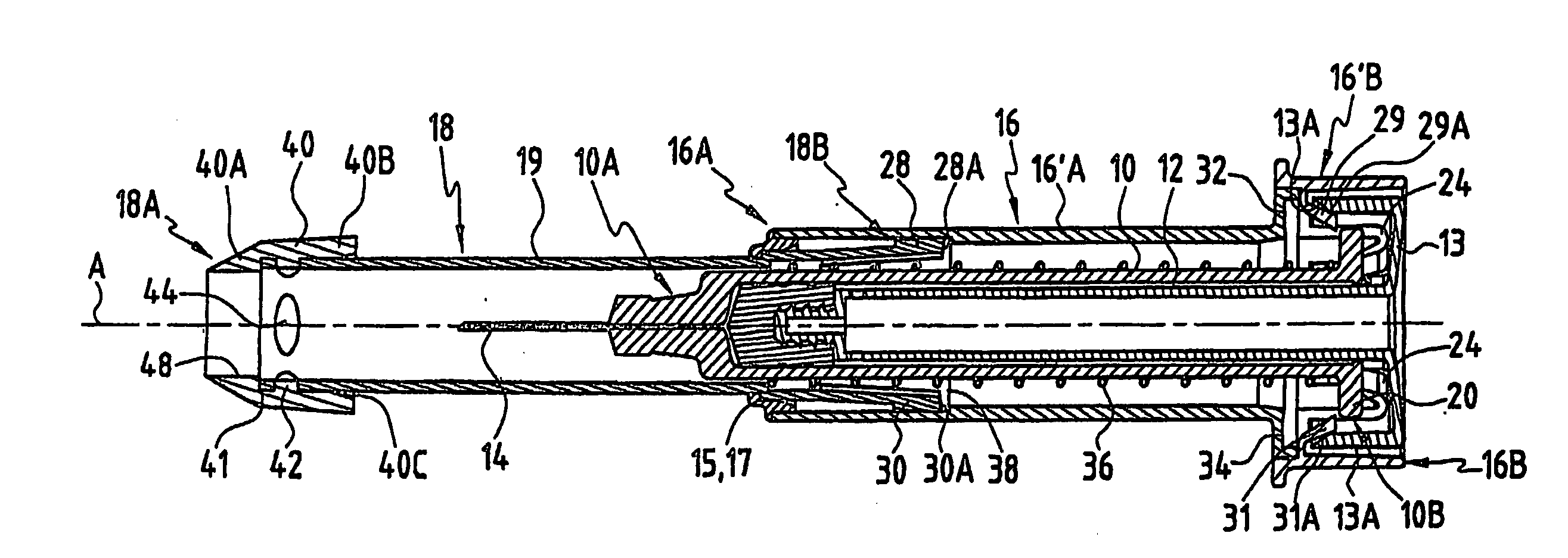
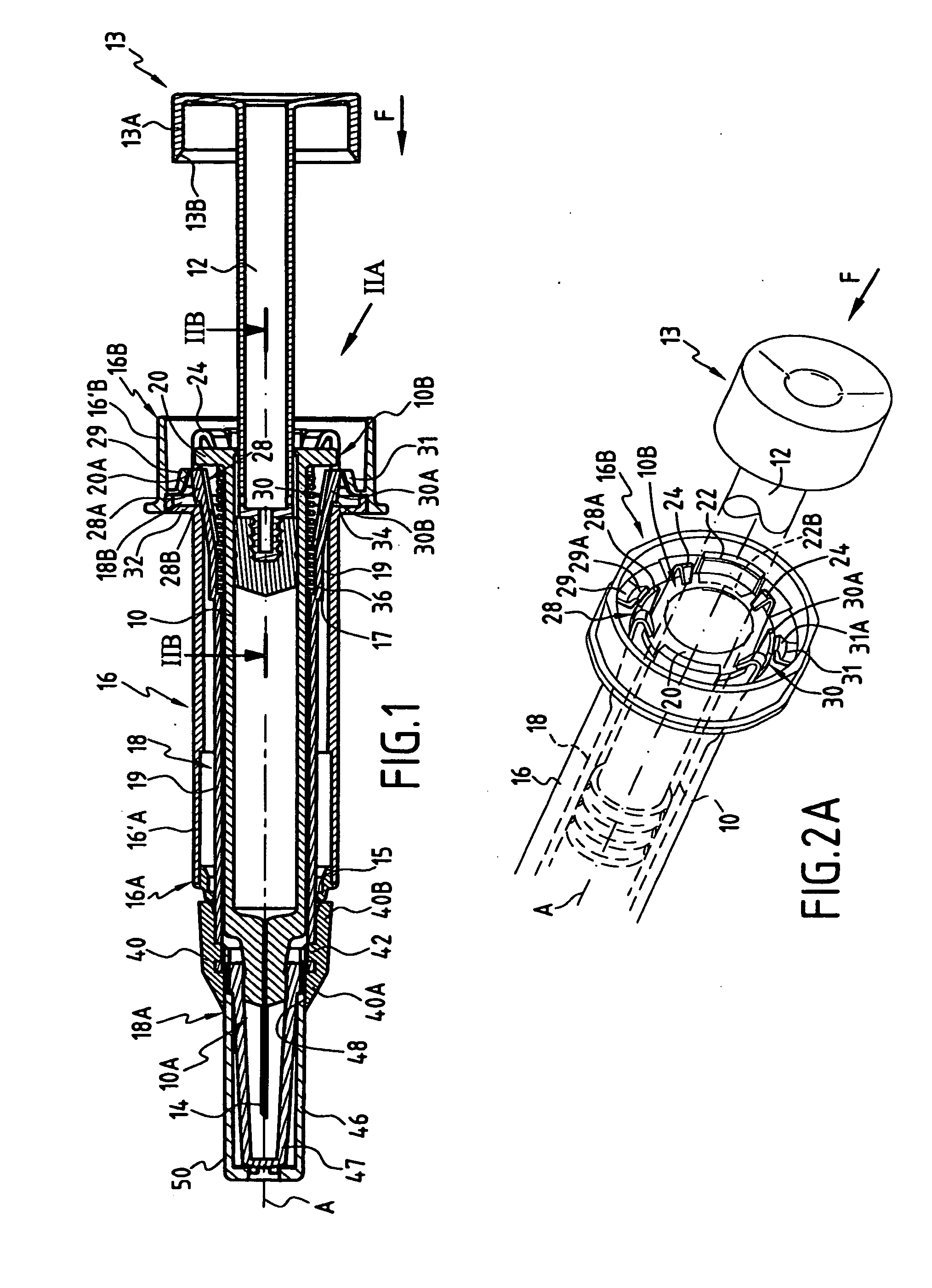
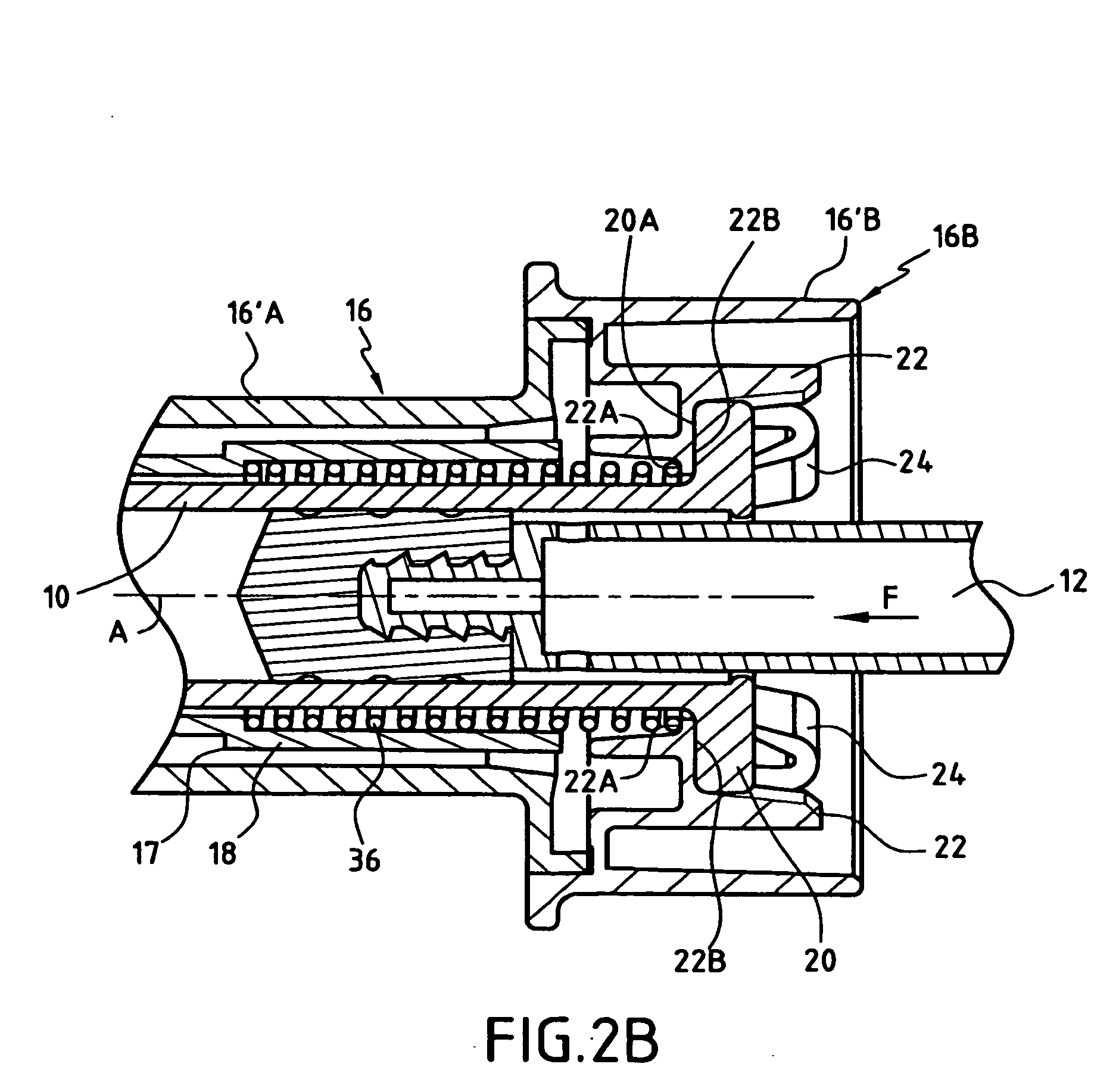
[0036]The syringe shown in FIGS. 1 to 4 has a body 10 in which a piston 12 is mounted to slide between a waiting-for-injection position shown in FIG. 1 and an end-of-injection position shown in FIGS. 3 and 4. At that end of the body which is remote from the piston, an injection needle 14 is connected to the body 10. The body of the syringe 10 is preferably made of glass or of plastic.

[0037]The safe support device for this syringe comprises a support outer sheath 16 and an inner sheath 18 that is mounted to slide between a waiting retracted position prior to injection, shown in FIG. 1, and an active protection position after injection, shown in FIGS. 3 and 4. In the waiting retracted position prior to injection, the inner sheath 18 is retracted into the outer sheath 16, i.e. it lies almost completely inside said outer sheath, while being disposed around the body 10 of the syringe and while being retained relative to the outer sheath 16 so that the needle 14 projects beyond the respec...


PUM


Abstract

The invention relates to a safe support device for a syringe, said support comprising a support sheath for the body of a syringe, and safety means which comprise an inner sheath suitable for sliding relative to said support sheath between a waiting retracted position, in which said inner sheath is substantially retracted inside said support sheath, and an active protection position, in which said inner sheath projects from said support sheath. The inner sheath has a free end portion formed by a flexible end-piece. The invention also relates to an assembly comprising such a safe support device and a syringe having a body, a piston and a needle disposed at one end of said body.

Description

[0001]The present invention relates to a safe support device for a syringe, said safe support device comprising a support sheath for the body of a syringe, and safety means which comprise an inner sheath suitable for sliding relative to said support sheath between a waiting retracted position, in which said inner sheath is substantially retracted inside said support sheath, and an active protection position, in which said inner sheath projects from said support sheath.[0002]The invention also relates to an assembly made up of such a device and of a syringe.[0003]Such a device makes it possible to protect the user against any risk of accidental pricking after the syringe has been used, and therefore against any risk of possible contamination, by surrounding the needle of the syringe with the inner sheath which is driven into its active protection position by drive means such as a spring.BACKGROUND OF THE INVENTION[0004]Such devices and assemblies that make it possible to protect the ...

Claims


Application Information

Patent Timeline
Patent Type & Authority Applications(United States)
IPC IPC(8): A61M5/32A61G12/00
CPCA61M5/326A61M2005/3143A61M5/3204A61M2005/3261A61M2005/3264A61M2005/3247A61M5/31511A61M5/3202
Inventor CHEVALLIER, STEPHANECHEVALLIER, JEAN-MICHEL
Owner SANOFI AVENTIS SA
Why Eureka
Try Eureka