Flexible stent with torque-absorbing connectors

a flexible stent and connector technology, applied in the field of medical devices, can solve the problems of reducing the density of the web, affecting the support of the stent, and limited support to the arterial walls

Active Publication Date: 2008-11-27
ABBOTT LAB VASCULAR ENTERPRISE
View PDF99 Cites 64 Cited by
  • Summary
  • Abstract
  • Description
  • Claims
  • Application Information

AI Technical Summary

Benefits of technology

[0022]The second segment may be rectilinear in shape and become twisted to acquire a helical curvature when a bending or expansion stress is applied to the stent. In one embodiment, the central element may be pre-deformed with a helical curvature in the contracted delivery configuration that becomes more accentuated during a bending or expansion of the stent. The central element may also be manufactured to have a cross-sectional area that is different from the cross-sectional areas of the end segments.

Problems solved by technology

Therefore, whenever stent flexibility is increased in the stents in the prior art, scaffolding support is affected negatively due to the related reduction in web density.
This arrangement provides for a stent with a high degree of longitudinal flexibility, but also for limited support to the arterial walls at the junctions areas between the different stent segments.
The stent of the '403 patent provides an elevated degree of scaffolding to the arterial walls, though its structure provides only for a limited degree of longitudinal flexibility due to the limited extent of longitudinal translation that is possible between web rings when a compressive force is applied.
This construction also provides for an elevated degree of scaffolding of the vessel walls, but its flexibility is constrained by the limited ability to compress of the flexible segments.
If the web rings are prevented from rotating, the torsional stress in the stent becomes absorbed by the flexible connectors and by the web rings, possibly causing the connectors to warp along their entire length.
Additionally, this type of construction causes a foreshortening of the stent during expansion.

Method used


Image

  • Flexible stent with torque-absorbing connectors
  • Flexible stent with torque-absorbing connectors
  • Flexible stent with torque-absorbing connectors

Examples


Embodiment Construction

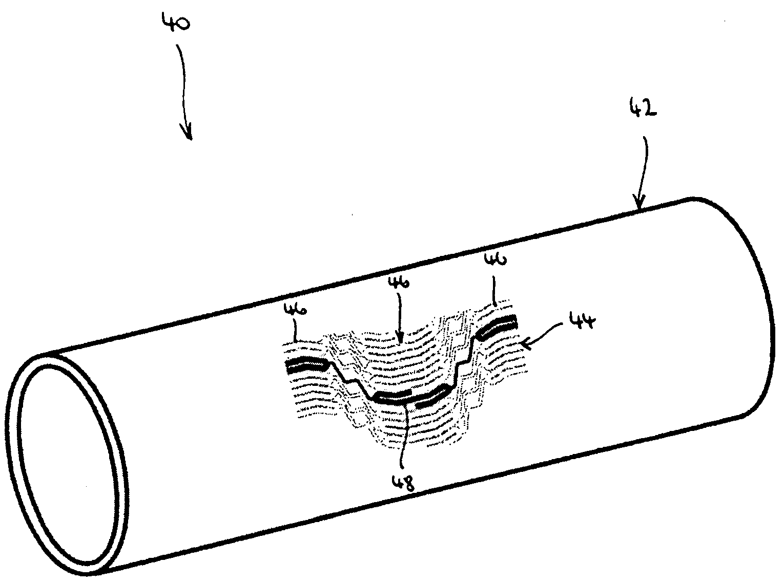
[0036]The present invention relates to stent designs that can absorb an elevated degree of torque during expansion and after implantation in a patient while at the same time providing a highly flexible stent structure. One application of the present invention relates to closed cell stents, in particular, carotid stents, for which an elevated degree of lesion scaffolding and the capability of conforming to tortuous anatomies are key design features.

[0037]Detailed descriptions of embodiments of the invention are provided herein. It is to be understood, however, that the present invention may be embodied in various forms. Therefore, the specific details disclosed herein are not to be interpreted as limiting, but rather as a representative basis for teaching one skilled in the art how to employ the present invention in virtually any detailed system, structure, or manner.

[0038]Referring to FIG. 4, a stent 40 constructed according to the principles of the present invention includes an ess...


PUM


Abstract

The present invention concerns a stent with a highly flexible structure that is configured to provide an elevated degree of vessel scaffolding and to absorb torque applied on the stent. In one embodiment, the stent of the present invention includes an essentially tubular body formed by a web structure that is composed of a plurality of longitudinally adjacent web rings, each including a plurality of web elements that are disposed circumferentially around the longitudinal axis of the stent and that are adjoined one to the other by a junction bend. Each junction bend in a first web ring is coupled to another junction bend in a neighboring ring by a connector having a step-wise configuration, in which a central segment of the connector is disposed essentially parallel to the longitudinal axis of the stent and may become twisted to absorb torque imposed on the stent.

Description

CROSS-REFERENCE TO RELATED APPLICATIONS[0001]The present application is a continuation in part application of U.S. patent application Ser. No. 11 / 805,584 filed on May 20, 2007, the entirety of which is incorporated herein by reference.FIELD OF THE INVENTION[0002]The present invention relates to a medical device. More particularly, the present invention relates to a flexible stent that provides elevated torque-absorbing properties.BACKGROUND OF THE INVENTION[0003]Atherosclerosis, sometimes called the hardening or clogging of the arteries, is an accumulation of cholesterol and fatty deposits, called plaque, on the inner walls of the arteries. Atherosclerosis causes a partial or total blockage of the arteries and, consequently, a reduced blood flow to the heart, legs, kidneys, or brain.[0004]Traditionally, clogged arteries have been treated with surgical procedures that involve the removal of the diseased arterial tract. Angioplasty procedures, during which a stent is inserted in the d...

Claims


Application Information

Patent Timeline
Patent Type & Authority Applications(United States)
IPC IPC(8): A61F2/06
CPCA61F2/915A61F2002/91541A61F2002/91558A61F2250/0031A61F2230/0069A61F2/86A61F2/89
Inventor CASEY, BRENDAN J.
Owner ABBOTT LAB VASCULAR ENTERPRISE
Why Eureka
Try Eureka