Mattress Construction with Filamentary Fasteners

Inactive Publication Date: 2008-12-04
KINGSDOWN INC
View PDF19 Cites 0 Cited by
  • Summary
  • Abstract
  • Description
  • Claims
  • Application Information

AI Technical Summary

Benefits of technology

[0014]An object of the invention is to

Problems solved by technology

The fastening methods described above generally do not permit much free play between the joined layers, and have other drawbacks.
F

Method used


Image

  • Mattress Construction with Filamentary Fasteners
  • Mattress Construction with Filamentary Fasteners
  • Mattress Construction with Filamentary Fasteners

Examples


Embodiment Construction

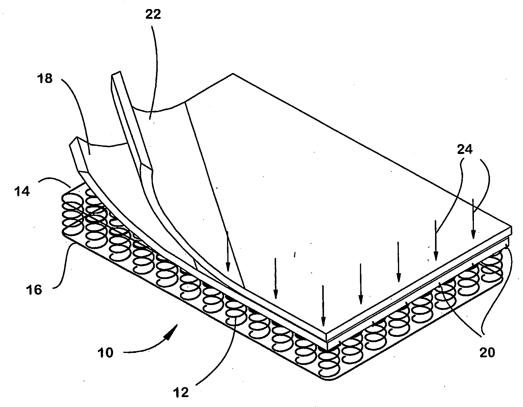
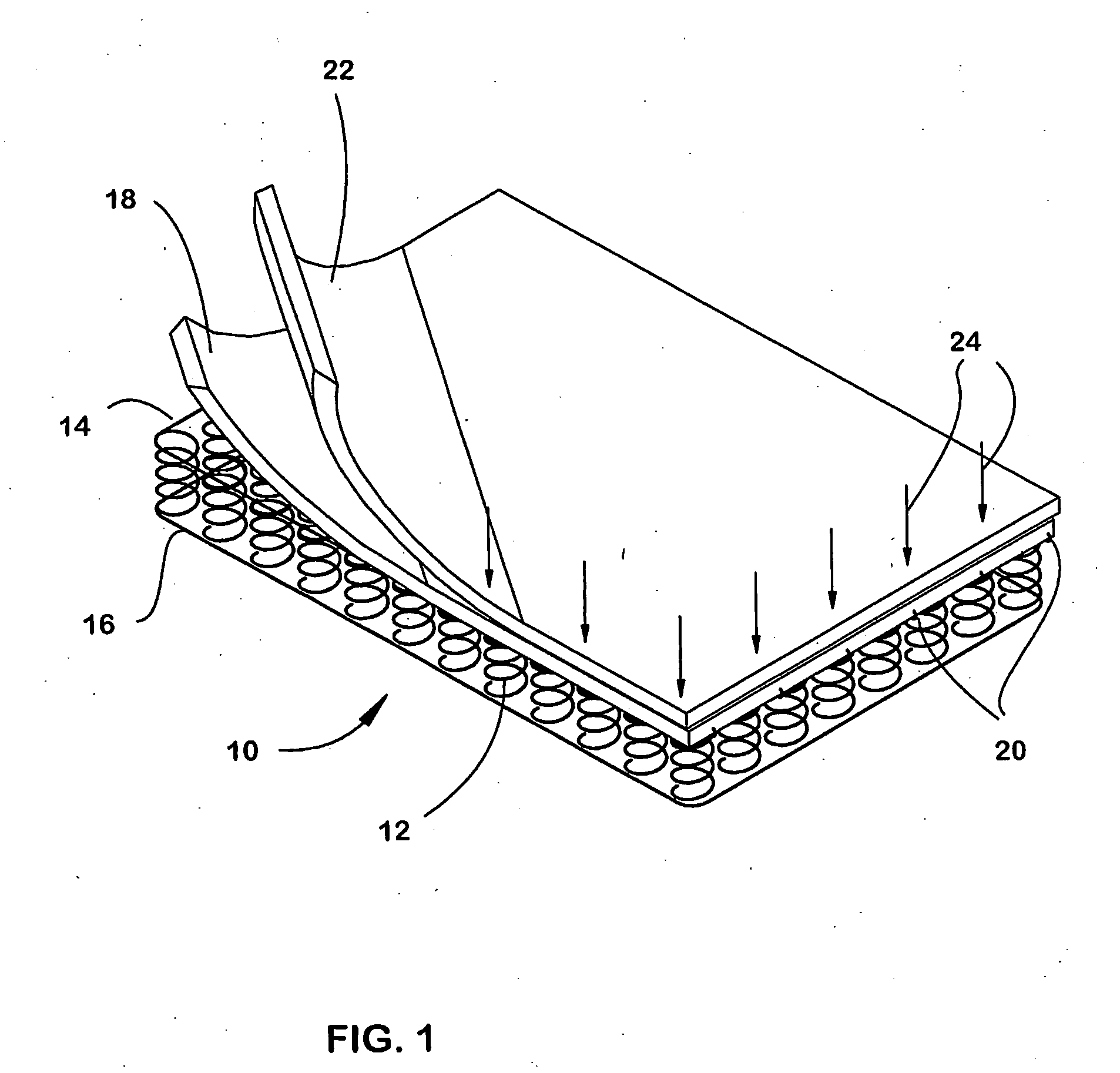
[0030]A mattress construction embodying the invention is shown in FIG. 1, which depicts a core element, in particular a metal innerspring unit 10, having an array of parallel coil springs 12 bounded top and bottom by respective border wires 14,16. It should be understood, however, that the invention is applicable to the manufacture of mattresses having other types of core elements. The core element may be, for example, a block of high density foam.

[0031]In the illustrated construction, at least one inner layer 18 of insulation is secured to the border wires, or to the coil springs, of the innerspring 10 by metal connectors such as hog rings 20 which are passed through the material and crimped around the underlying metal component, or by other means such as adhesives. The inner layer may be bonded fiber batting, or a non-fibrous material such as a polymeric foam.

[0032]At least one outer layer 22 of insulation is then placed on top of the inner layer or layers, and is secured to the i...


PUM

PropertyMeasurementUnit
Angleaaaaaaaaaa
Flexibilityaaaaaaaaaa

Abstract

At least one major surface of the core is covered with an inner layer of insulation, and at least one outer layer of material. The outer layer is secured to the inner layer by inserting flexible filament type fasteners through the hollow needle of an installation tool. If the core is made of foam, filamentary fasteners may also be used to secure the inner layer. The insulation layers are ultimately covered and secured in place by a fabric panel which conceals and secures the other components. Filamentary fasteners may also be used to secure a pillow top edge or a top panel to the mattress.

Description

BACKGROUND OF THE INVENTION[0001]This invention relates to a mattress and a method of making mattresses.[0002]In conventional mattress construction, a metal innerspring unit—usually having an array of parallel coil springs surrounded top and bottom by respective border wires which define the edges of the mattress—is covered with layers of padding and fabric. Modern synthetic padding is commonly called “insulation”. Some of the insulation may be secured to the border wires, or to the coil springs, by metal connectors such as hog rings which are passed through the material and crimped around the underlying metal component. Other insulation layers may be attached at least temporarily by the use of adhesives or sewing. The insulation layers are ultimately covered and secured in place by a fabric panel which conceals the other components and presents a finished appearance.[0003]Not all mattresses contain innersprings. Some, for example, have a high density foam core, or an air bladder. A...

Claims


Application Information

Patent Timeline
IPC IPC(8): A47C23/04B68G7/05B68G7/12
CPCA47C31/026B68G7/08Y10T29/481B68G15/00Y10T29/488B68G7/085A47C27/00
Inventor CECIL, DAVID SCOTT
Owner KINGSDOWN INC
Why Eureka
Try Eureka