
Blasting device

a technology of a blasting device and a nozzle, which is applied in the field of blasting devices, can solve the problems of affecting the function and service life of the cubicle, the construction does not offer sufficient assurance of the cubicle being closed, and the creation of dust, so as to reduce the risk of dust escap

Inactive Publication Date: 2008-12-04
SIEMENS AG
View PDF7 Cites 1 Cited by
  • Summary
  • Abstract
  • Description
  • Claims
  • Application Information

AI Technical Summary

Benefits of technology

[0006]It is, therefore, the object of the present invention to create a blasting device in which the escape of dust from the blasting cubicle is effectively prevented.
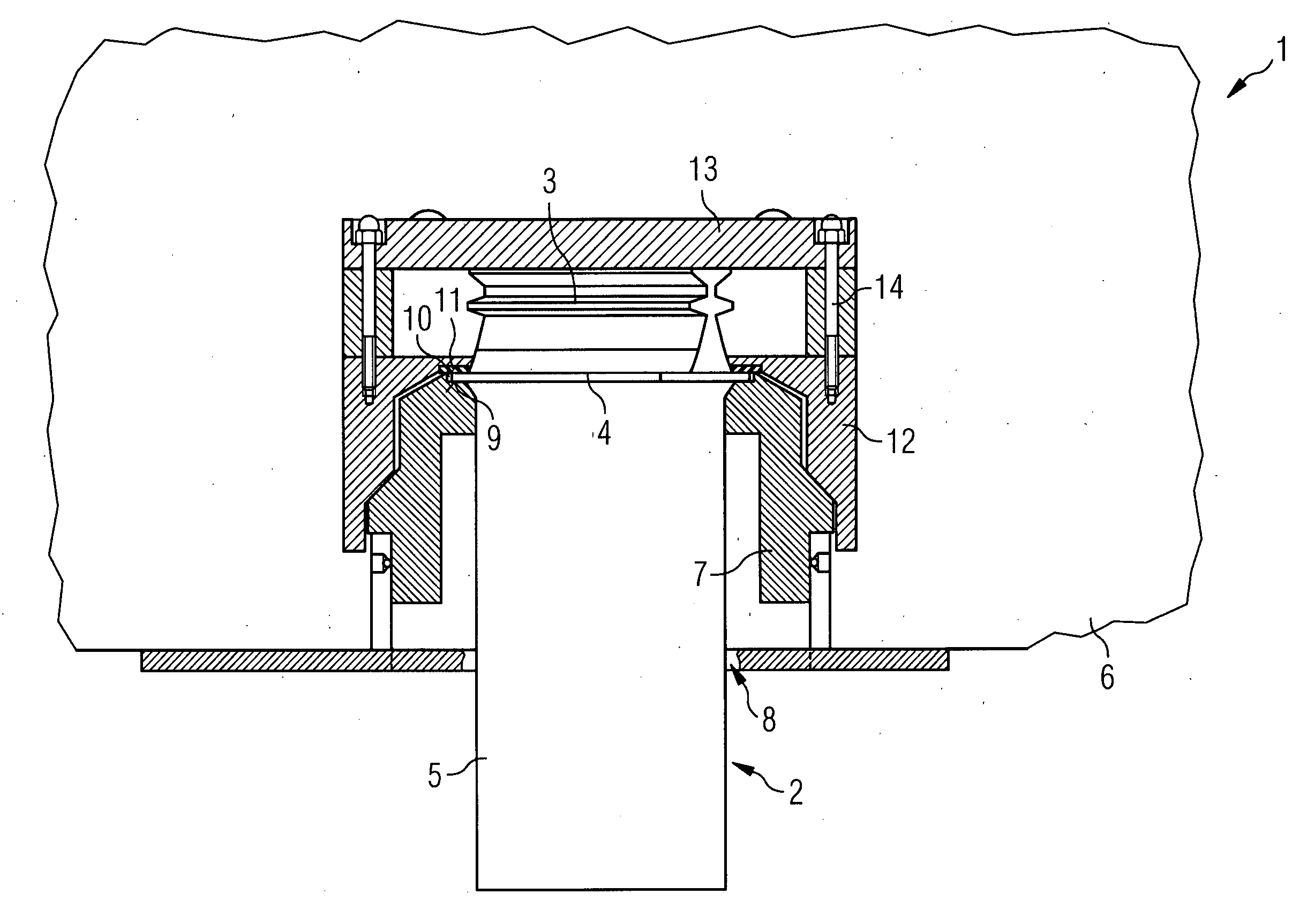
[0008]Since the seal according to the invention is arranged on the inner side of the cubicle, the penetration of dust into the gap is already effectively prevented. In this way, it is ensured that no dust from the cubicle can get to the blade airfoil.
[0011]A cap, which on the inner side of the chamber fits over the blade platform and the seal, can also be provided. The cap advantageously protects the seal against the blasting media which is present in the cubicle. As a result of this, in particular the service life of the seal is increased, since this is no longer worn away during the blasting process.
[0013]It is also possible to provide for the seal to be fastened on the cap. As a result of this, a quick, accurate and simultaneous assembly of the cap and of the seal is possible. Furthermore, slipping of the seal is prevented. In order to facilitate the exchange and the maintenance of the seal, it can especially be detachably fastened on the cap.
[0017]A large-pore foam can be used as sealing material. This material is especially suitable since on the one hand it ensures high sealing integrity, and on the other hand has a sufficient resistibility and therefore also a long service life.
[0019]In order to still further reduce the risk of escape of dust from the cubicle, a suction device can also be provided. This continuously removes the dust which is created from the cubicle.

Problems solved by technology

A significant problem when blasting turbine blades is that the dust which is created in the course of this can escape from the cubicle and can get onto the ceramic coating of the blade airfoil.
As a result of this, its function and service life is negatively affected.
However, this construction does not offer sufficient assurance that the cubicle is closed off in an altogether dustproof manner.

Method used


Image

  • Blasting device
  • Blasting device

Examples


Embodiment Construction

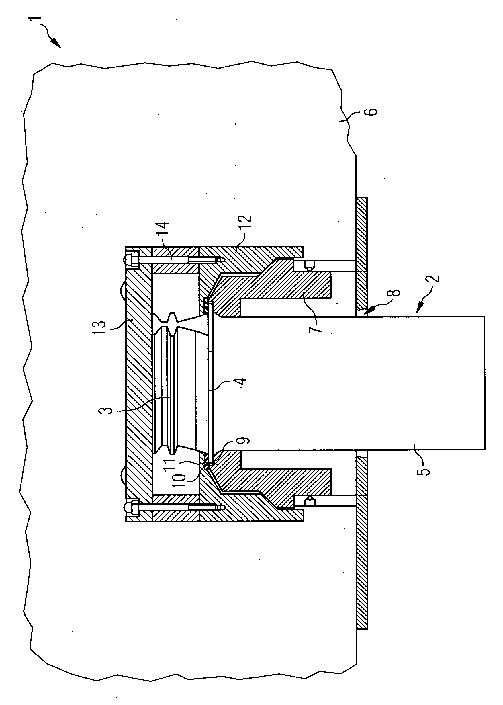
[0023]In FIG. 1, a schematic representation of a blasting device 1 according to the invention for blasting a part of a turbine blade 2 is shown. The turbine blade 2 comprises a blade root 3, a blade platform 4 and a blade airfoil 5.

[0024]The blasting device 1 has a blasting cubicle 6, a blasting unit, which is connected to it, but not shown, for the discharge of accelerated blasting media, and a mounting 7 for the turbine blade 2.

[0025]An insertion opening 8 is formed in the blasting cubicle 6, through which is guided the blade airfoil 5 of the turbine blade 2. The mounting 7 is arranged inside the blasting cubicle 6, surrounding the insertion opening 8, wherein it holds the turbine blade 2 in a vertically suspended manner. For this purpose, a locating surface 9 is formed on the mounting 7, upon which the surface of the blade platform 4 which points away from the blasting cubicle 6 bears in areas. As a result of this, a gap 10, which extends to the insertion opening 8, is formed bet...


PUM

PropertyMeasurementUnit
thickaaaaaaaaaa
thickaaaaaaaaaa
thickaaaaaaaaaa

Abstract

Disclosed is a blasting device for blasting a part of a turbine blade, which has a blade root, a blade platform and a blade airfoil, with a blasting cubicle, which has an insertion opening, a blasting unit for the discharge of accelerated blasting media into the blasting cubicle, and a mounting for the turbine blade, wherein a seal is provided, which seals a gap between the mounting and the blade airfoil in the region of the insertion opening and so prevents the escape of dust, which is created when blasting, from the blasting cubicle, and wherein the seal seals the gap from the inner side of the cubicle.

Description

CROSS REFERENCE TO RELATED APPLICATIONS[0001]This application claims the benefits of European application No. 07007545.2 filed Apr. 12, 2007 and is incorporated by reference herein in its entirety.FIELD OF INVENTION[0002]The present invention relates to a blasting device for blasting a part of a turbine blade, which has a blade root, a blade platform and a blade airfoil, with a blasting cubicle which has an insertion opening, a blasting unit for the discharge of accelerated blasting media into the blasting cubicle, and a mounting for the turbine blade, wherein a seal is provided, which seals a gap between the mounting and the blade airfoil in the region of the insertion opening and so prevents the escape of dust, which is created when blasting, from the blasting cubicle.BACKGROUND OF THE INVENTION[0003]Such a blasting device is described in US 2006 / 0021410 A1. This device is provided for blasting the blade root and the side of the blade platform of a turbine blade which faces the bl...

Claims


Application Information

Patent Timeline
Patent Type & Authority Applications(United States)
IPC IPC(8): C21D7/06
CPCB24C1/04B24C1/10
Inventor HOELZEL, FALKOMULLER, JEANPAPE, MICHAEL
Owner SIEMENS AG
Learn More