Punch press die holder with hand-operated retaining clamp

a technology of retaining clamp and punch press, which is applied in the field of punch press die holder, can solve the problems of inapplicable circular die methods, inability to manually remove or replace circular dies that are in wide-scale commercial use, and laborious and time-consuming

Inactive Publication Date: 2008-12-04
MATE PRECISION TOOLING
View PDF14 Cites 24 Cited by
  • Summary
  • Abstract
  • Description
  • Claims
  • Application Information

AI Technical Summary

Problems solved by technology

Consequently, the placement and removal of a die requires the use of hand tools and is therefore labor intensive and time consuming.
Although methods have been proposed to facilitate more rapid removal of noncircular dies, i.e. those that are octagonal, rectangular, etc., these methods are not applicable to circular dies.
Thus, there has been no way to manually remove or replace circular dies that are in wide scale commercial use, that is to say without the use of hand tools.
In addition, the die must be inserted or removed from the side since the top of the die holder is obstructed by the upper turret.
It has been calculated that in the course of a day, a typical punch press operator may spend as much as two hours removing and replacing dies, and of course the press is out of production during this period.

Method used


Image

  • Punch press die holder with hand-operated retaining clamp
  • Punch press die holder with hand-operated retaining clamp
  • Punch press die holder with hand-operated retaining clamp

Examples


Embodiment Construction

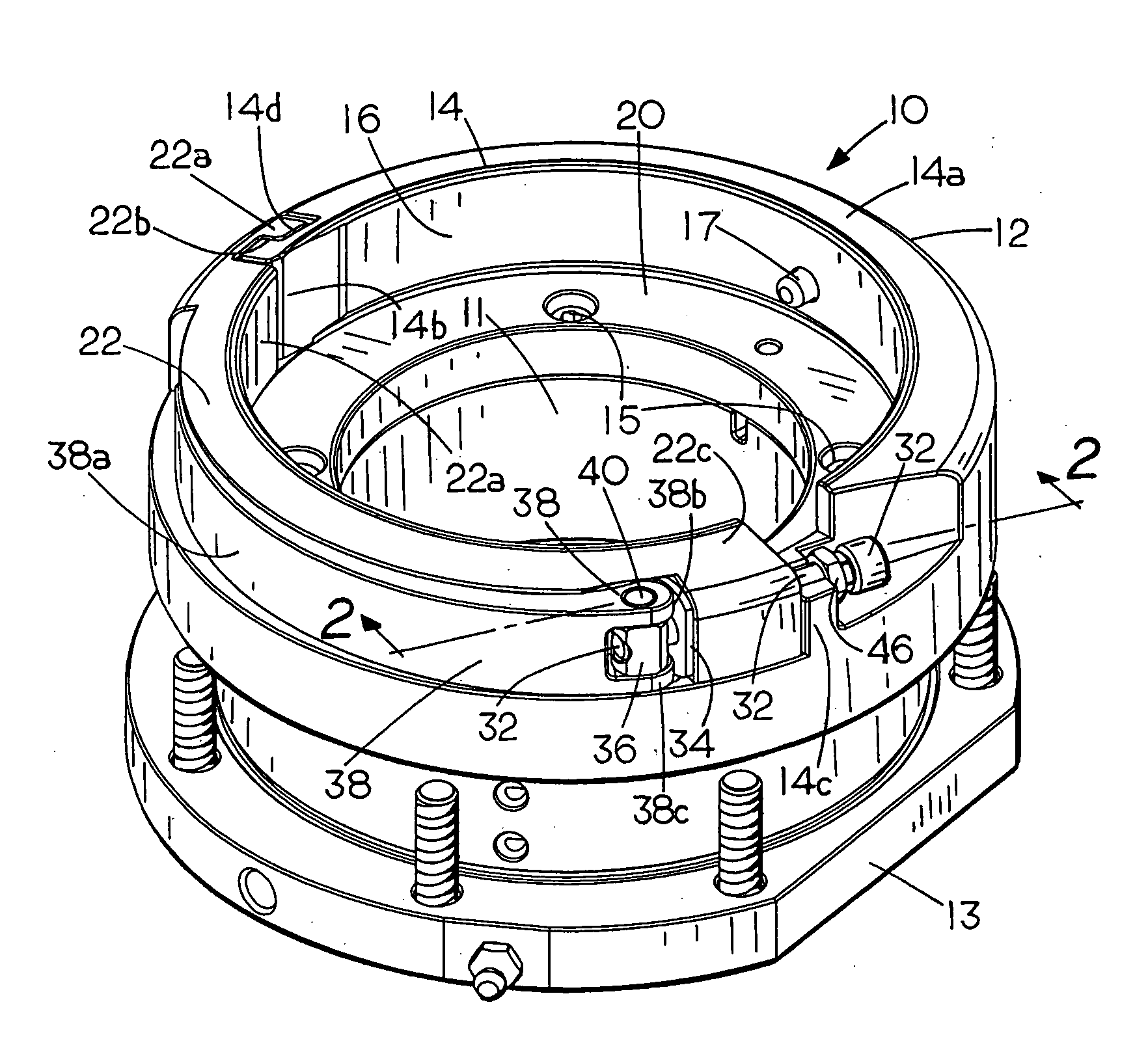
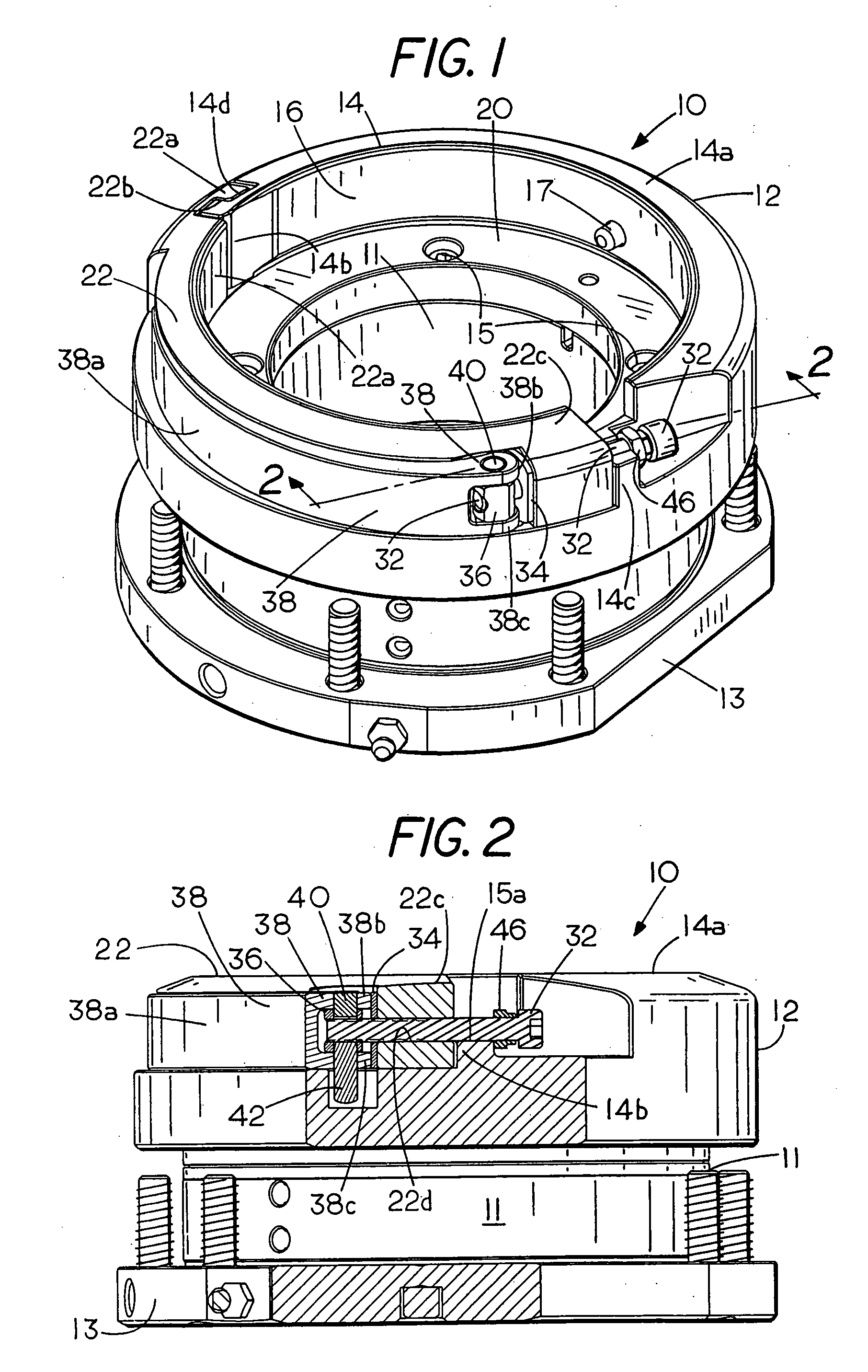
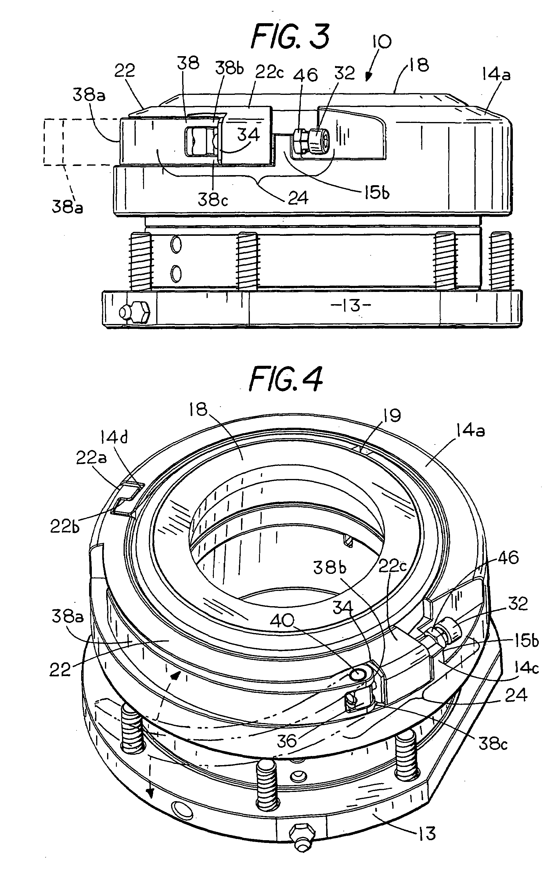
[0023]Refer now to the Figs., and particularly to FIGS. 1-4 which show a punch press die holder assembly 10 having an annular die holder body 12 with a circular rim 14 surrounding a generally cylindrical die receptacle or die socket 16. The die holder 10 is mounted on the punch press (not shown) in any suitable manner, e.g. using a base plate 13 of conventional well-known construction. The die holder 10 has a downwardly extending inner sleeve 11 of conventional construction that is journaled for rotation in the base plate 13. Sleeve 11 can be secured to the lower portion of receptacle 16 by fasteners such as cap screws 15 (FIG. 1). The receptacle 16 is dimensioned to receive the circular punch press die 18 (FIG. 4). At the bottom of the receptacle 16 of the die holder assembly 10 is a circular die-supporting surface 20 (FIGS. 1 and 7) for limiting the downward movement of a die 18 when the die is mounted for operation within the receptacle 16 as shown in FIG. 4. Receptacle 16 has a ...


PUM

PropertyMeasurementUnit
angleaaaaaaaaaa
pressureaaaaaaaaaa
timeaaaaaaaaaa

Abstract

A punch press die holder assembly includes a die holder body with a fixed rim which partially surrounds an upwardly opening die receptacle within the die holder. The receptacle is dimensioned to receive a punch press die, especially of any various circular dies now in commercial use. Cooperating with the fixed rim portion of the die holder is a moveable clamp member that is a portion of the rim that has a centrally directed surface which contacts the die when the die is in place within the receptacle. A manually operable fastener is operatively connected to the moveable clamp member to hold the clamp member in a closed position for restricting the movement of the die and the fastener is movable by hand to an open position for releasing the clamp member and the die from the die holder so that the die can then be removed and replaced from one side by sliding it horizontally out of the die holder.

Description

[0001]Applicants hereby claim the benefit of corresponding provisional application Ser. No. 60 / 932,420, filed May 30, 2007 which is incorporated herein in its entirety.FIELD OF THE INVENTION[0002]This invention relates to the punch and die art and more particularly to an improved die holder for a punch press.BACKGROUND OF THE INVENTION[0003]In the punch and die art and particularly in the field of high-speed automated forming and punching equipment for punching and forming a workpiece, e.g., sheet metal and especially in the case of automated turret punch presses, the punch presses are operated by computer to rapidly perform a series of punching or forming operations sequentially. These punch presses which by themselves form no part of the present invention are typically provided with aligned upper and lower turrets that rotate and are indexed intermittently between punching operations. The turrets may hold as many as a dozen or more separate punches that are used in sequence for pe...

Claims


Application Information

Patent Timeline
Patent Type & Authority Applications(United States)
IPC IPC(8): B21D37/00
CPCB21D28/34
Inventor THIELGES, BRUCE M.THELL, ALEX M.
Owner MATE PRECISION TOOLING
Why Eureka
Try Eureka