Punch capable of punching and embossing simultaneously

a technology of punching and embossing, applied in the field of punching, can solve the problems of inability to work with complex designs and irregular embossing patterns

Inactive Publication Date: 2005-09-29
DN CRAFT
View PDF13 Cites 26 Cited by
  • Summary
  • Abstract
  • Description
  • Claims
  • Application Information

AI Technical Summary

Benefits of technology

[0012] According to another aspect of the invention, there is also provided a punch, which includes a jig having a cutting hole of a predetermined pattern, and a punching area on which a convex embossment (or, a concave embossment) of a predetermined pattern is formed at a position adjacent to the cutting hole; a base to which the jig is fixed, the base giving a support surface so that a sheet member to be punched is supplied to the punching area; a punching member having punch pins for punching and embossing the supplied sheet member with moving up and down against the jig; and an elastic body interposed between the punching member and the

Problems solved by technology

In addition, when using each punch, the user may measure a punching point and an embossing point just with the eye whenever conducting the

Method used


Image

  • Punch capable of punching and embossing simultaneously
  • Punch capable of punching and embossing simultaneously
  • Punch capable of punching and embossing simultaneously

Examples


Embodiment Construction

[0029] Hereinafter, the present invention will be described in more detail referring to the drawings.

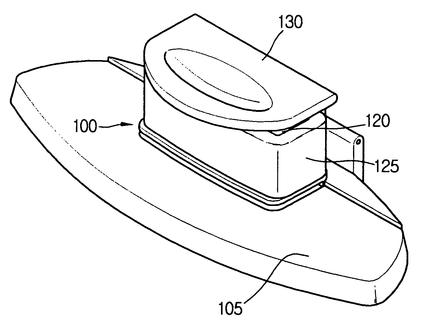
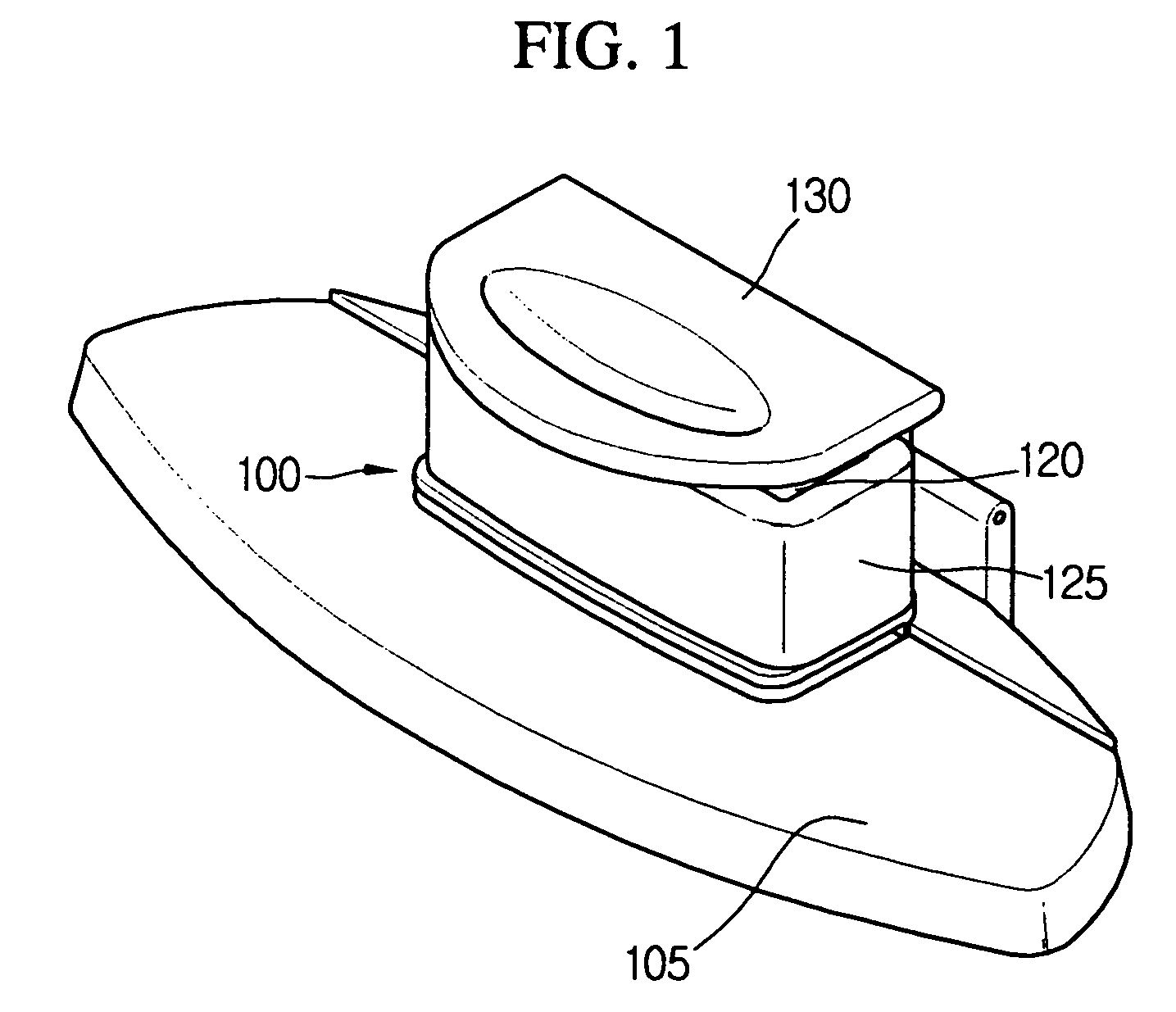
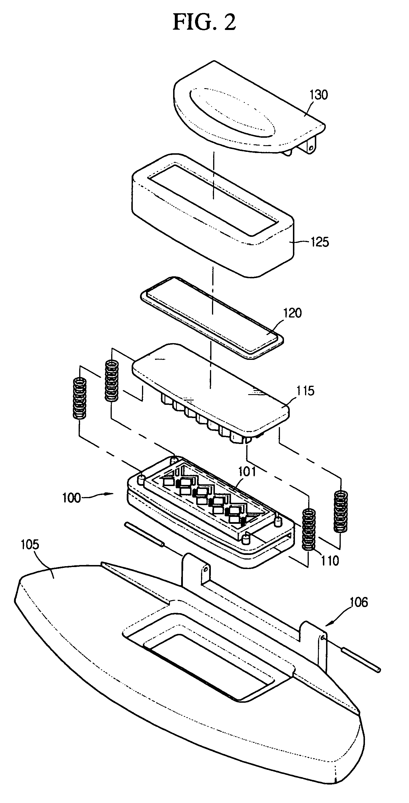
[0030]FIG. 1 is an exploded perspective view showing a punch according to a preferred embodiment of the present invention, and FIG. 2 is a perspective view showing the punch of FIG. 1 in an assembled state.

[0031] Referring to FIGS. 1 and 2, the punch of the present invention includes a jig 100 having a punching area 101, a base 105 for supporting the jig 100, a punching member 115 for punching and embossing a sheet member supplied to the jig 100 with selectively descending against the jig 100, and a handle 130 used for pressing the punching member 115.

[0032] The jig 100 supports the supplied sheet member and gives the punching area 101 for punching and embossing the sheet member in a predetermined pattern. As exemplarily shown in FIG. 3, the punching area 101 of the jig 100 has at least one cutting hole 101a of a predetermined pattern and at least one convex embossment 102 of a pr...


PUM

PropertyMeasurementUnit
Lengthaaaaaaaaaa

Abstract

A punch capable of simultaneously punching and embossing a sheet member such as a card, a letter paper, a picture, a board, or a paper in a predetermined pattern is disclosed. The punch includes a jig having a cutting hole of a predetermined pattern and a punching area on which a convex embossment is spaced apart from the cutting hole; a base for fixing the jig and giving a support surface to supply a sheet member to the punching area; a punching member including a first punch pin having a cutting blade corresponding to the cutting hole and a second punch pin having a concave embossment corresponding to the convex embossment, the punching member punching and embossing the supplied sheet member with moving vertically against the jig; and an elastic body interposed between the punching member and the jig to bias the punching member upward.

Description

BACKGROUND OF THE INVENTION [0001] 1. Field of the Invention [0002] The present invention relates to a punch, and more particularly to a punch capable of simultaneously punching and embossing a sheet member such as a card, a letter paper, a picture, a board, or a paper in a predetermined pattern. [0003] 2. Description of the Related Art [0004] A punch generally includes a jig having a cutting hole of a predetermined pattern, a base for supporting the jig below it, and a punching member having a sharp cutting blade which slides through the cutting hole of the jig. This punch punches a sheet member according to the pattern of the cutting hole when the punching member passes through the jig by means of the stroke operation for descending the punching member toward the jig while the predetermined sheet member is put into a corresponding punching area of the jig. [0005] In the punch configured as mentioned above, it is also possible to form an embossing design of a predetermined pattern ...

Claims


Application Information

Patent Timeline
IPC IPC(8): B26D5/08B26F1/36B31F1/07
CPCB26D3/10B31F1/07B26F1/36Y10T83/8785Y10T83/8834B26F1/38
Inventor OH, WAN-YOUNG
Owner DN CRAFT
Why Eureka
Try Eureka