High speed digital communication networks for high interference cargo transportation environments

a high-interference, cargo technology, applied in powerline communications applications, transportation items, hoisting equipment, etc., can solve the problems electrical interference, reduce the capabilities and functionalities of ethernet over copper technology, etc., to achieve more reliable communication and high throughput data rate

Inactive Publication Date: 2008-12-04
INNOVATIVE AMERICAN TECH
View PDF84 Cites 10 Cited by
  • Summary
  • Abstract
  • Description
  • Claims
  • Application Information

AI Technical Summary

Benefits of technology

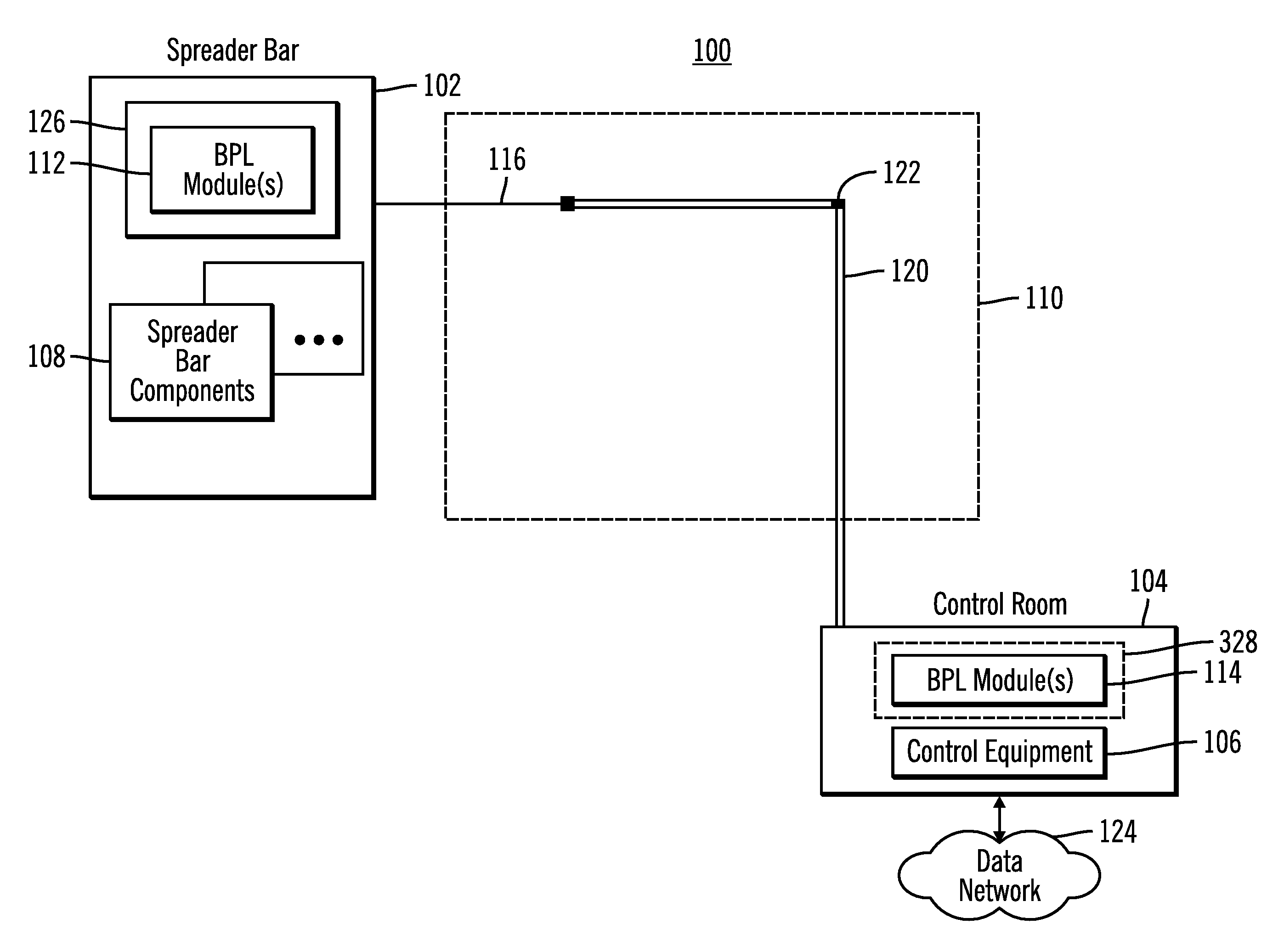
[0014]One advantage of the various embodiments of the present invention is that high speed networks can be deployed within a high interference cargo transportation environment such as shipping yards, train yards, stations, and the like. These high speed networks are created using power line wires existing between cargo coupling components such as (but not limited to) a spreader bar of a gantry crane to other parts of the cargo moving system such (but not limited to) a gantry crane control room. These high speed networks, according to the present invention, are much more resistant to the large amounts of interference experienced in such harsh environments than conventional networking technologies used in the past. Therefore, the various embodiments of the present invention provide much higher throughput data rates and more reliable communication than what has been available in the past.

Problems solved by technology

The Ethernet over copper technology is problematic because data transfer speeds generally do not exceed 100 kbps (typically 50 kbps) within the gantry crane environment.
This is due to the enormous amount of interference that exits within the gantry crane environment and the shipping yard itself.
This interference can be (but is not limited to) radio frequency interference (RFI), electromagnetic interference (EMI), and mechanical shock and vibration resulting in electrical interference.
This harsh environment drastically reduces the capabilities and functionalities of Ethernet over copper technology.
The increased bandwidth is difficult to attain due to the high interference environment, which includes those interferences discussed above, and other interferences such as from other high voltage cables in close proximity to the data communication cables and heavy duty motors that cause interference on the copper lines.
However, installing fiber optic technology on moving devices for transporting and handling cargo is expensive and difficult to maintain in the aggressive environment of a port, train yard, station, or other cargo delivery environment.
Furthermore, wireless technology is sometimes used, but experiences large amounts of interference in these harsh environments as well.
Furthermore, wireless technologies do not provide the level of security generally required for particular applications being performed in these types of environments.

Method used


Image

  • High speed digital communication networks for high interference cargo transportation environments
  • High speed digital communication networks for high interference cargo transportation environments
  • High speed digital communication networks for high interference cargo transportation environments

Examples


Embodiment Construction

[0020]As required, detailed embodiments of the present invention are disclosed herein; however, it is to be understood that the disclosed embodiments are merely examples of the invention, which can be embodied in various forms. Therefore, specific structural and functional details disclosed herein are not to be interpreted as limiting, but merely as a basis for the claims and as a representative basis for teaching one skilled in the art to variously employ the present invention in virtually any appropriately detailed structure and function. Further, the terms and phrases used herein are not intended to be limiting; but rather, to provide an understandable description of the invention.

[0021]The terms “a” or “an”, as used herein, are defined as one or more than one. The term plurality, as used herein, is defined as two or more than two. The term another, as used herein, is defined as at least a second or more. The terms including and / or having, as used herein, are defined as comprisin...


PUM


Abstract

A communication link arrangement for a cargo moving device comprises an electrical infrastructure that is mechanically coupled to a cargo moving device. The cargo moving device includes a cargo retaining structure and a main body coupled to the cargo retaining structure. The electrical infrastructure includes a single conductor electrically coupling the cargo retaining structure and the main body for delivering power and data signals between the cargo retaining structure and the main body. The electrical infrastructure further includes one or more conductors. A first networking element is mechanically coupled to the cargo retaining structure and is electrically coupled to the single conductor. A second networking element is mechanically coupled the main body and is also electrically coupled to the single conductor. A high-speed network link over power line carries data over the single conductor in the electrical infrastructure that supplies power between the main body and the cargo retaining structure.

Description

CROSS-REFERENCE TO RELATED APPLICATIONS[0001]This application is based on, and claims priority from, prior co-pending U.S. Provisional Patent Application No. 60 / 932,687 filed on Jun. 1, 2007, by inventor David L. FRANK, and entitled “GANTRY CRANE TO SPREADER BAR HIGH SPEED DIGITAL COMMUNICATIONS”, and further is based on, and claims priority from, prior co-pending U.S. Provisional Patent Application No. 60 / 933,851 filed on Jun. 9, 2007, by inventor David L. FRANK, and entitled “GANTRY CRANE TO SPREADER BAR AND GANTRY CRANE TO DATA NETWORK HIGH SPEED DIGITAL COMMUNICATIONS”, the entire collective disclosure of all the above-identified applications being hereby incorporated by reference.BACKGROUND OF THE INVENTION[0002]1. Field of the Invention[0003]The present invention generally relates to the field of high speed digital communications, and more particularly relates to providing a high speed digital networking environment on cargo moving devices experiencing high interference.[0004]...

Claims


Application Information

Patent Timeline
Patent Type & Authority Applications(United States)
IPC IPC(8): B66F9/06B66C1/00H04B3/00B66C5/02
CPCB66F9/06H04B3/542H04B2203/5445H04B2203/545
Inventor FRANK, DAVID L.
Owner INNOVATIVE AMERICAN TECH
Why Eureka
Try Eureka