Controlling method and controlling apparatus for starting clutch

a control method and clutch technology, applied in the direction of clutches, non-mechanical actuated clutches, coupling-brake combinations, etc., can solve the problems of waste throttling, less efficiency of torque converters, and large slippage, so as to facilitate the parking operation of vehicles on and facilitate the parking operation on the road having the slope and/or step

Inactive Publication Date: 2008-12-04
NSK WARNER
View PDF2 Cites 2 Cited by
  • Summary
  • Abstract
  • Description
  • Claims
  • Application Information

AI Technical Summary

Benefits of technology

[0015]By variably controlling the pressing force of the piston of the starting clutch, since the torque which is wished by the driver can be transmitted to wheels of the vehicle, a low speed running operation such as a parking operation of the vehicle on the slope can be facilitated. As a result, the parking operation on the road having the slope and / or step is facilitated in comparison with the conventional parking operations.

Problems solved by technology

On the other hand, the torque converter has a disadvantage that a large amount of slip is generated during the torque transmission and, thus, the torque converter has less efficiency.
Although the starting clutch has excellent performance, since there is clearance between the friction engaging elements in a clutch released or disengaged condition, upon starting the vehicle, when an acceleration pedal is depressed, a time difference is generated between the depression of the acceleration pedal and the engagement of the starting clutch until the starting clutch is engaged, thereby arising problems that waste throttling is generated and that shock is apt to be generated upon the engagement of the clutch.
However, if there is a slope and / or a step in the route to the parking area, the vehicle cannot be moved by the conventional creep force and, thus, it is required to move the vehicle backwardly by depressing the acceleration pedal.
As a result, it is difficult to adjust the depression of the acceleration pedal and the timing of the braking.

Method used


Image

  • Controlling method and controlling apparatus for starting clutch
  • Controlling method and controlling apparatus for starting clutch
  • Controlling method and controlling apparatus for starting clutch

Examples


Embodiment Construction

[0023]Now, an embodiment of the present invention will be fully explained with reference to the accompanying drawings. Incidentally, it should be noted that the embodiment described hereinbelow is merely an example of the present invention and that various alterations can be made.

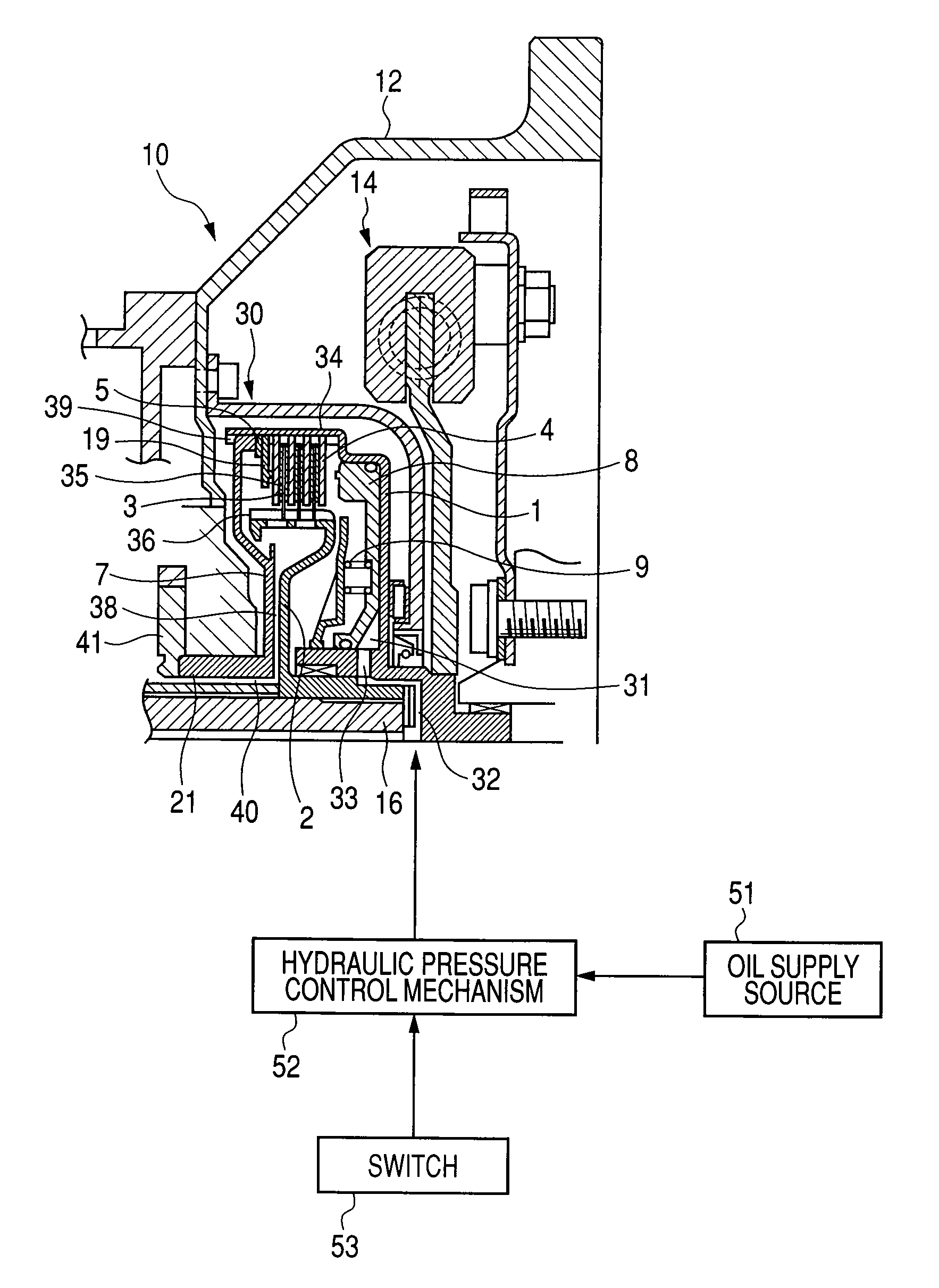
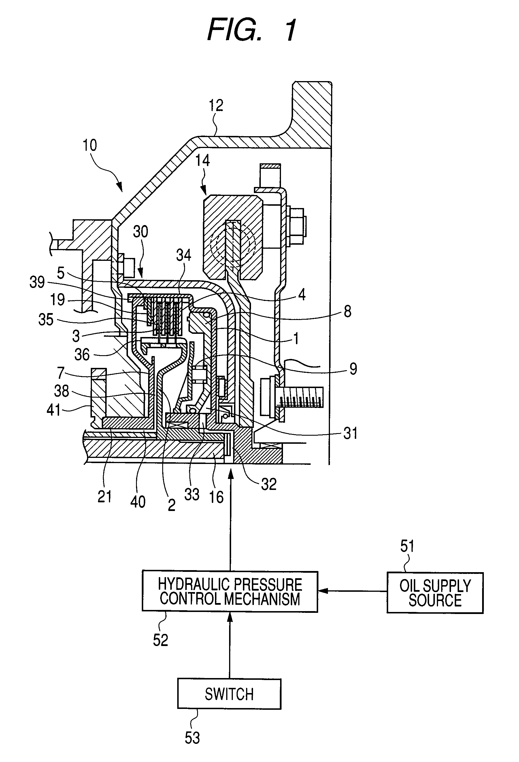
[0024]FIG. 1 is an axial sectional view of a starting clutch, for explaining an embodiment of controlling method and apparatus for the starting clutch according to the present invention. A starting clutch 10 includes a clutch drum or clutch case 1 and a wet type multi-plate clutch 30 housed in the clutch case. Within the clutch case 1, substantially annular friction plates 3 as friction engaging elements at an output side of the wet type multi-plate clutch 30 and substantially annular separator plates 4 as friction engaging elements at an input side are arranged alternately along an axial direction. At an axial one end (open end) of the clutch case 1, a substantially annular backing plate 19 is fixedly supp...


PUM


Abstract

The present invention provides a controlling method for a starting clutch disposed between a transmission and an engine of a vehicle and having a wet type multi-plate clutch for transmitting a power and a piston for pressing the wet type multi-plate clutch to engage the wet type multi-plate clutch, wherein, while the starting clutch is being subjected to creep control, the pressing force of the piston is controlled variably.

Description

BACKGROUND OF THE INVENTION[0001]1. Field of the Invention[0002]The present invention relates to a controlling method and a controlling apparatus for a starting clutch used as a starting device of an automobile and the like.[0003]2. Related Background Art[0004]Conventionally, in automatic transmissions i.e. ATs, the starting of a vehicle was performed by transmitting torque through a torque converter. The torque converter was mounted to many AT vehicles since the torque converter has a torque amplifying effect and provides smooth torque transmission.[0005]On the other hand, the torque converter has a disadvantage that a large amount of slip is generated during the torque transmission and, thus, the torque converter has less efficiency.[0006]Therefore, in recent years, there has been proposed a technique in which a starting clutch is used in place of the torque converter, and the torque has been amplified at a low speed range by reducing a gear ratio and by increasing the number of s...

Claims


Application Information

Patent Timeline
Patent Type & Authority Applications(United States)
IPC IPC(8): F16D25/00
CPCF16D48/066F16D2500/31433F16D2500/31453F16D2500/31466F16D2500/31493F16D2500/50221F16D2500/70217F16D2500/1024F16D2500/1025F16D2500/10437F16D2500/1085F16D2500/3023F16D2500/3024F16D2500/3101F16D2500/3111F16D2500/50206F16D2500/70211
Inventor NARUSE, TOSHIHIROSAKAI, MASAKIMIYAZAKI, TOMOYUKI
Owner NSK WARNER
Why Eureka
Try Eureka