Contactless power transferring apparatus

a technology of power transfer apparatus and contactless connection, which is applied in the direction of emergency power supply arrangement, transportation and packaging, inductance, etc., can solve the problems of falling transmission power, affecting the shape (design) of the terminal mount of the cradle and the mobile terminal, and affecting the transmission power

Active Publication Date: 2008-12-04
SONY MOBILE COMM INC +1
View PDF1 Cites 19 Cited by
  • Summary
  • Abstract
  • Description
  • Claims
  • Application Information

AI Technical Summary

Benefits of technology

[0017]That is, according to an embodiment of the invention, the opening of the terminal loading portion is larger than the outer form of the mobile terminal, and inside the terminal loading portion, the mobile terminal is supported from at least three directions that are the width direction, the thickness direction, and the up-down direction so that the primary coil and the secondary coil are aligned. This means that according to an embodiment of the invention, by merely inserting the mobile terminal into the terminal loading portion, it is possible to align the center positions of the primary coil and the secondary coil and simultaneously dispose the coils a predetermined distance apart.
[0018]According to an embodiment of the invention, it is possible to align the center positions of a primary coil and a secondary coil and simultaneously dispose the coils a predetermined distance apart by merely inserting a mobile terminal into a terminal loading portion of a contactless power transferring apparatus. Therefore, when carrying out contactless power transferring, the user may not need to carry out a difficult operation such as aligning the center positions of the coils. Also, according to an embodiment of the invention, the opening of the terminal mounting portion has a sufficient size for loading a plurality of types of mobile terminal of different outer forms, sizes, and the like, and a construction that simultaneously carries out positioning in the width direction, the thickness direction, and the up-down direction of the mobile terminal is also provided inside the terminal loading portion. Accordingly, it is possible to transfer power to a variety of types of mobile terminal with few restrictions on the form of the mobile terminal and the form of the terminal loading portion, and therefore it is not necessary for the user to buy a new cradle every time the user buys a new mobile terminal, for example.

Problems solved by technology

When contactless power transferring using electromagnetic induction is employed as the method of transferring power from a cradle to a mobile terminal, electric contacts between the cradle and the mobile terminal may be unnecessary.
However, when the center positions of both the contactless power transferring coil provided in the cradle and the contactless power transferring coil provided in the mobile terminal become greatly displaced or the separation distance between the coils is too great, there is a fall in the transmission power.
This means that in reality, the disposed position when the mobile terminal is mounted on the terminal mount of the cradle may be limited, and the form (design) of the terminal mount of the cradle and the form (design) of the mobile terminal may also be restricted.
However, it may be difficult for a user to place the mobile terminal on the terminal mount of the cradle so that the displacement between the center positions of the coils is within the range of a few millimeters.

Method used


Image

  • Contactless power transferring apparatus
  • Contactless power transferring apparatus
  • Contactless power transferring apparatus

Examples


Embodiment Construction

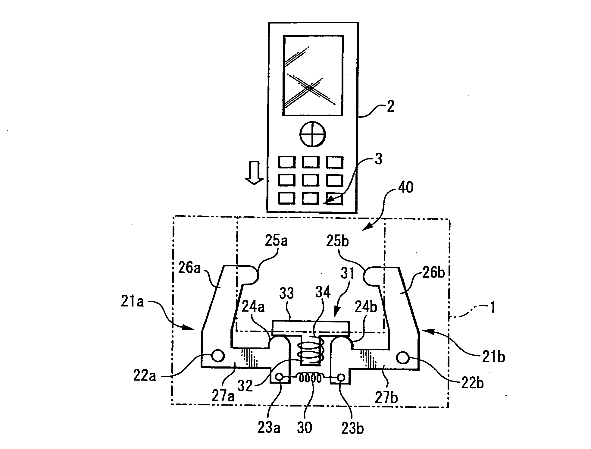
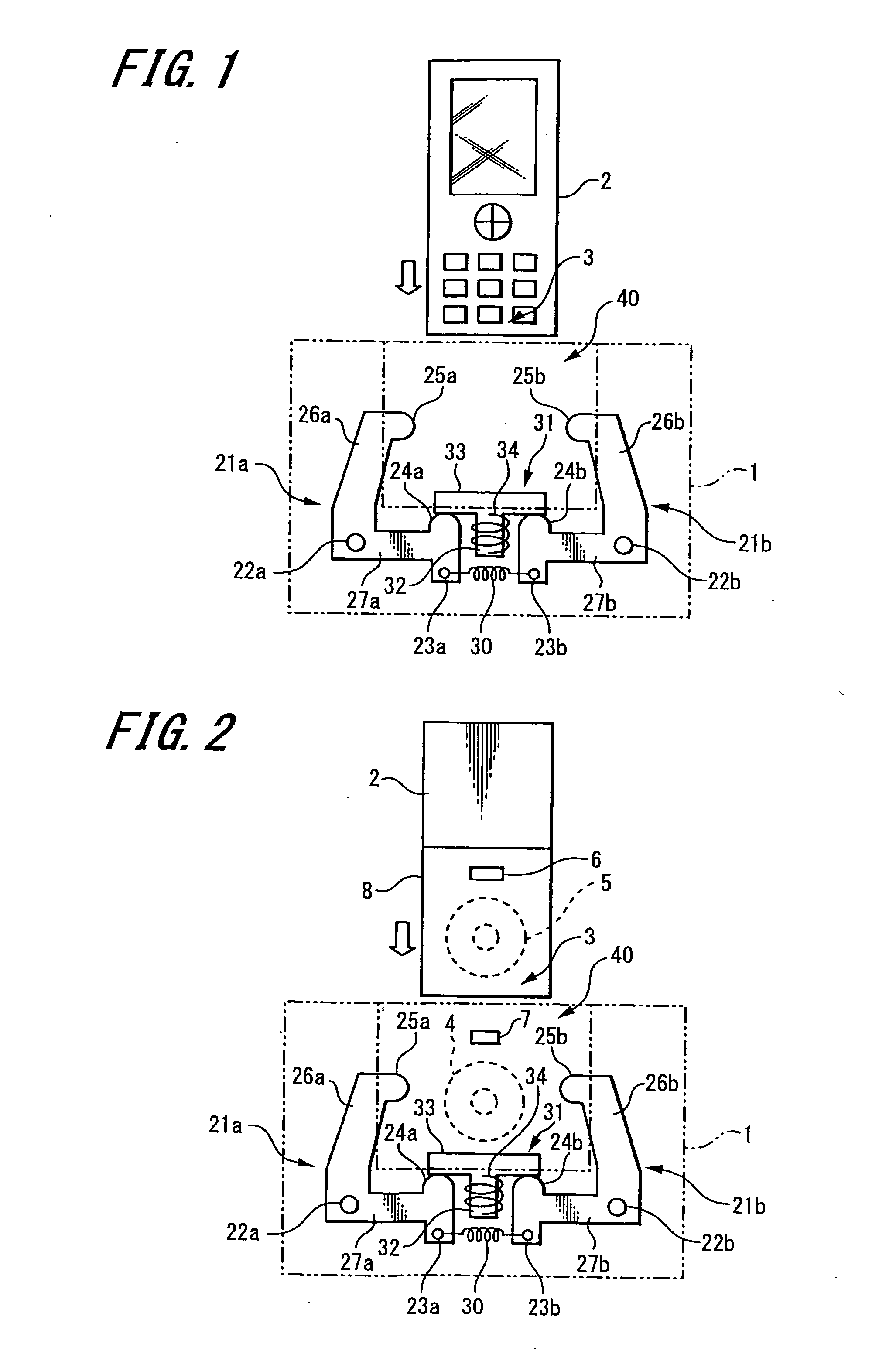
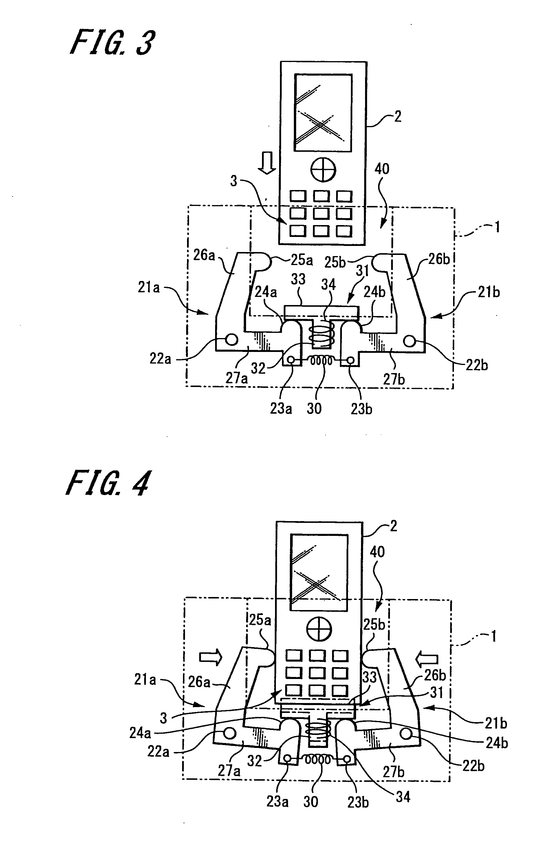
[0040]Preferred embodiments of the invention will now be described with reference to the attached drawings.

[0041]In the present embodiment, a cradle that uses a flat coil as a primary-side contactless power transferring coil and transfers power using electromagnetic induction to a flat coil (“secondary coil”) provided in a mobile phone unit that is one example of a mobile terminal according to an embodiment of the invention is described as one example of a contactless power transferring apparatus according to an embodiment of the invention. The primary-side contactless power transferring coil is formed by winding a linear conductor made of a solid wire, a twisted wire, or flat pattern, into a spiral on a substantially flat plane. Similarly, a system formed of the mobile phone unit and the cradle is given as an example of a contactless power transferring system according to an embodiment of the invention. However, it should be appreciated that the details of such cradle and system ar...


PUM


Abstract

A contactless power transferring apparatus includes a terminal loading portion, a primary coil, an up-down-direction pressing portion, a width direction pressing portion and a thickness direction pressing portion. The terminal loading portion has an opening through which a mobile terminal is inserted and loaded. The primary coil transfers power using electromagnetic induction to a secondary coil incorporated in the mobile terminal. When the mobile terminal is inserted inside the terminal loading portion, the pressing portions operate in an up-down direction, in a left-right direction and in a width direction, to press and support the mobile terminal respectively from below to position the coils in the up-down direction, from the width direction to position the coils in the left-right direction and from the thickness direction to dispose the coils a predetermined distance apart.

Description

CROSS REFERENCES TO RELATED APPLICATIONS[0001]The present invention contains subject matter related to Japanese Patent Application JP 2007-140886 filed in the Japanese Patent Office on May 28, 2007, the entire contents of which being incorporated herein by reference.BACKGROUND OF THE INVENTION[0002]1. Field of the Invention[0003]The present invention relates to a contactless power transferring apparatus that transfers power using electromagnetic induction via a contactless power transferring coil when charging a secondary cell incorporated in a small mobile terminal such as a mobile phone unit.[0004]2. Description of the Related Art[0005]An existing system that transfers charging power for charging a secondary cell incorporated in a mobile terminal, for example, via a contactless power transferring coil using electromagnetic induction is known.[0006]Japanese Unexamined Patent Application Publication No. 2001-60998 discloses a construction where contactless power transferring is carr...

Claims


Application Information

Patent Timeline
Patent Type & Authority Applications(United States)
IPC IPC(8): H02J17/00H02J7/00H04M1/02H04M1/21H04M1/215
CPCH02J7/0044H02J7/025H02J50/10H02J50/90
Inventor KATO, HIROSHISUZUKI, KUNIHARUSUZUKI, KATSUYAYAMAZAKI, MANABUKONDO, YOICHIROONISHI, KOTAYODA, KENTAROJIN, MIKIMOTO
Owner SONY MOBILE COMM INC
Why Eureka
Try Eureka