Rotating Electric Machine and Electrically Driven Vehicle

a technology of electric vehicles and rotating electric machines, which is applied in the direction of magnetic circuit rotating parts, magnetic circuit shape/form/construction, cycles, etc., can solve the problems of difficult to apply this invention to the motor of an electric vehicle, inability to move a rotating rotor, and inability to precisely control, so as to reduce attraction and repulsion, increase attraction and repulsion, and easily and reliably adjust the gap

Inactive Publication Date: 2008-12-04
YAMAHA MOTOR CO LTD
View PDF47 Cites 0 Cited by
  • Summary
  • Abstract
  • Description
  • Claims
  • Application Information

AI Technical Summary

Benefits of technology

[0020]It is therefore an object of an embodiment of the present invention to provide an electric rotating machine and electric vehicle that allow output characteristics to be freely and easily adjusted and modified while running.
[0031]As described above, according to certain aspects of the present invention, it is possible to easily and reliably adjust the gap between the rotor and stator, and therefore possible to actively adjust the relative positions of the rotor and stator, and by increasing attraction and repulsion generated between the two when high torque is necessary, and decreasing attraction and repulsion generated between the two when fast rotation is necessary, it is possible to freely change output characteristics.

Problems solved by technology

HEI 9-37598, precise control is not possible since the rotor is displaced by a solenoid.
Consequently, it is difficult to apply this invention to the motor of an electric vehicle, which requires precise control according to the driving force and vehicle speed.
HEI 9-37598, an example is shown in which the stator is moved by a motor and screw, but with this configuration it is not possible to move a rotating rotor.

Method used


Image

  • Rotating Electric Machine and Electrically Driven Vehicle
  • Rotating Electric Machine and Electrically Driven Vehicle
  • Rotating Electric Machine and Electrically Driven Vehicle

Examples


first embodiment

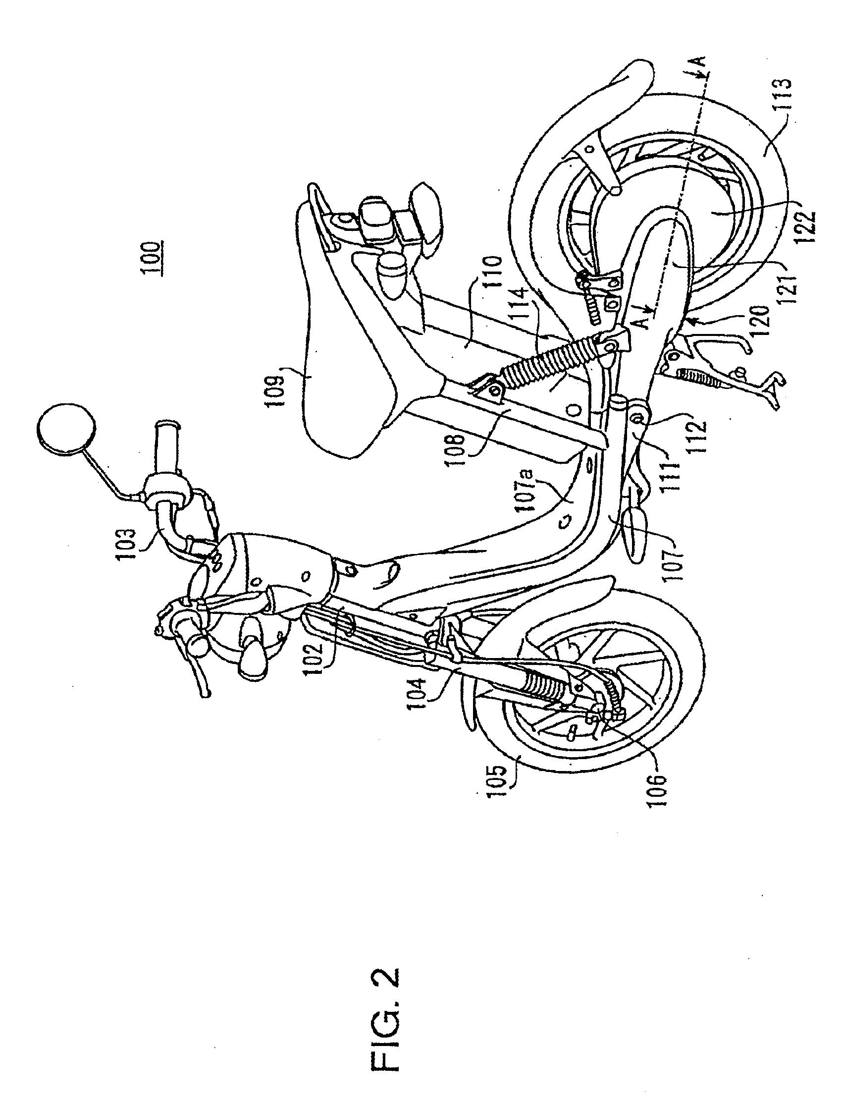
[0044]FIG. 2 is a side view of an electric two-wheeled vehicle to which an electric rotating machine is applied. Electric two-wheeled vehicle 100 shown in FIG. 2 has head tube 102 provided on the upper front part of its vehicle body, and a steering shaft (not shown) passes through the inside of this head tube 102 in a freely rotatable fashion. Handlebars 103 are attached to the top end of this steering shaft, and the upper parts of a pair of left and right front forks 104 are connected to the bottom end. Front wheel 105 is pivoted in a freely rotatable fashion at the bottom ends of these front forks 104 by a front wheel axle 106.

[0045]A pair of left and right vehicle body frames 107 extending toward the rear of the vehicle body are joined to head tube 102.

[0046]Vehicle body frames 107 have a round tubular shape, and after extending obliquely downward from head tube 102 toward the rear of the vehicle body, are curved in an arc shape toward the rear, and extend approximately horizont...

second embodiment

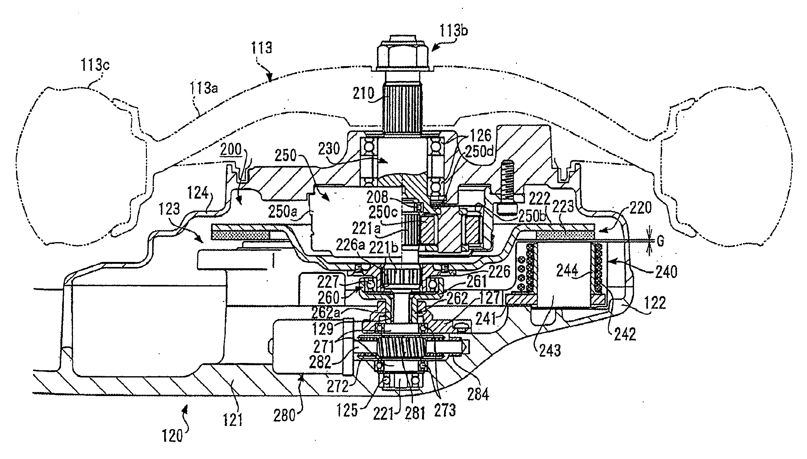
[0145]FIG. 6 is a cross-sectional drawing showing the principal parts of an electric rotating machine. Electric rotating machine 300 shown in FIG. 6 is installed inside the housing of the swing arm unit instead of electric rotating machine 200 in the electric vehicle shown in FIG. 2.

embodiment 1

[0146]Referring to FIG. 2, FIG. 6 corresponds to the A-A line cross-sectional drawing in FIG. 2 in the same way as for the parts shown in FIG. 3. Components in Embodiment 1, or components having equivalent functions, are assigned the same reference numerals in FIG. 6, and only points of difference are described here.

[0147]As with electric rotating machine 200, by an adjustment mechanism that adjusts the relative positions of rotor 220 and stator 240 (gap G), electric rotating machine 300 shown in FIG. 6 can easily change output characteristics according to the running state, even while the vehicle is running. As compared with electric rotating machine 200, electric rotating machine 300 has an identical configuration except for the configuration of the rotating member, the position of the adjustment motor and springs.

[0148]That is to say, together with adjustment motor 380 and rotating member 370, electric rotating machine 300 shown in FIG. 6 has rotating shaft 230, speed reducer 250...


PUM


Abstract

A rotating electric machine whose output characteristics can be easily and freely adjusted and varied even in operation. The rotating electric machine is received in a housing of an electrically driven two-wheeled vehicle. A rotating shaft is connected to a rotor so as to form an axle. A stator is positioned opposite a rotor. A movable member is connected to a rotating member rotated about the rotating shaft by a regulating motor. The movable member is moved in the axial direction of the rotating shaft by the rotation of the rotating member. This movement causes the rotor to be rotatingly moved in the axial direction o the rotating shaft, changing relative position of the rotor and the stator.

Description

PRIORITY INFORMATION[0001]This application is a divisional of U.S. application Ser. No. 11 / 499,293 filed Aug. 4, 2006, which is a continuation of International Application PCT / JP2005 / 001333, with an international filing date of Jan. 31, 2005, which claims priority under 35 U.S.C. § 119(a)-(d) to Japanese Patent Application No. 2004-031379, filed Feb. 6, 2004, the entire contents of these applications are hereby expressly incorporated by reference herein.BACKGROUND OF THE INVENTION[0002]1. Field of the Invention[0003]The present invention relates to an electric rotating machine and electric vehicle whose output characteristics can be freely adjusted.[0004]2. Description of the Related Art[0005]Japanese Patent Application Laid-Open No. HEI 9-37598 relates to a control apparatus of a generator for a vehicle. In this invention, a radial gap motor is provided with an axial direction displacement mechanism that adjusts the gap between the stator and rotor. This axial direction displacemen...

Claims


Application Information

Patent Timeline
Patent Type & Authority Applications(United States)
IPC IPC(8): H02K21/12B60L15/20B62M7/12H02K7/06H02K7/12H02K21/24
CPCB60G2204/30H02K7/12B62K2204/00Y02T10/7258H02K21/24B60L2200/12Y02T10/64Y02T10/72
Inventor NAITO, SHINYAHINO, HARUYOSHIMUROTA, KEIKO
Owner YAMAHA MOTOR CO LTD
Why Eureka
Try Eureka