Lighting System Comprising Interconnectable Lighting Modules
- Summary
- Abstract
- Description
- Claims
- Application Information
AI Technical Summary
Benefits of technology
Problems solved by technology
Method used
Image

Examples
first embodiment
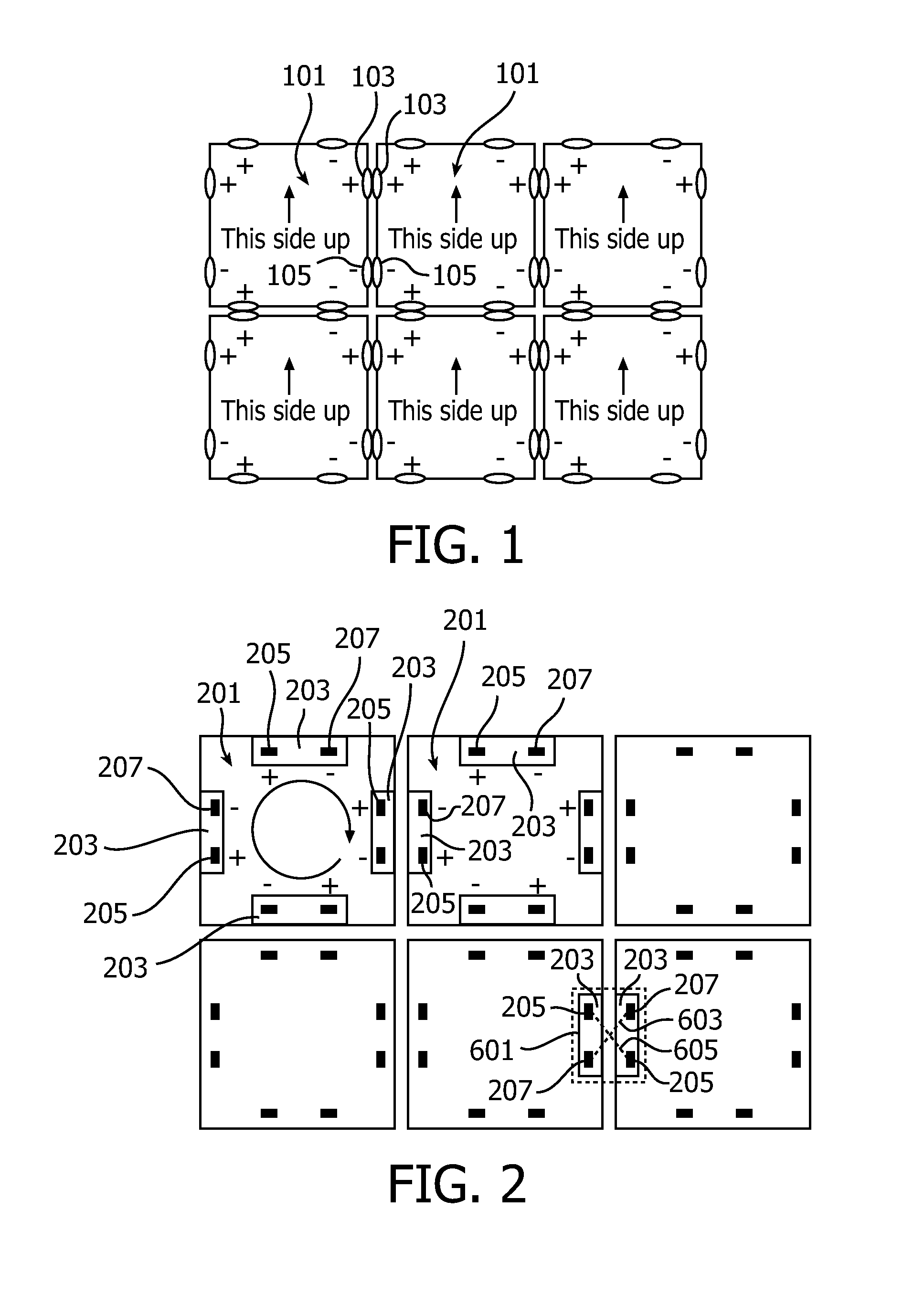
[0033]In accordance with the present invention the polygonal, here square, lighting modules 201, as shown in FIG. 2, of the lighting system are designed as follows. Each lighting module 201 is provided with a DC connection member 203 at each side thereof. Internally of the lighting module 201 the DC connection members 203 are connected in parallel to internal circuitry. Each DC connection member 203 comprises connection terminals including a positive terminal 205 and a negative terminal 207. All positive terminals 205 of the lighting module 201 are connected with each other, and so are all negative terminals 207 as well. The connection members 203 of each lighting module 201 are equally directed, and the connection terminals 205, 207 are alternately arranged, as regards the terminal polarities, along a circumference of the lighting module 201, for example clockwise as indicated by the circular arrow. Thus, the connection members 203 are symmetrically arranged at all sides of the lig...
second embodiment
[0038]According to an advantageous second embodiment of the lighting system, as shown in FIG. 7, a lighting module 701 comprises merely corner connection members 703 and corner bridge members 705, also shown at 1101 in FIG. 11. Each corner connection member 701 consists of a corner connection terminal 703, shown at 1105 in FIG. 11. The corner connection terminals 703, 1105 are alternately interconnected. For example, in the shown embodiment where the lighting modules 701 are squared, the corner connection terminals 703, 1105 are interconnected in pairs diagonally of the lighting module 701. The corner bridge member 1101 has four legs, constituting corner bridge terminals 1103, which are mountable at corner connection terminals 1105. All the corner bridge terminals 1103 are interconnected. Thus, the corner bridge member 705, 1101, at a maximum, interconnects four corner connection terminals, one on each lighting module of four neighboring modules 701, thereby feeding a power of a cer...
third embodiment
[0042]Referring now to FIG. 8, in the lighting system each lighting module 801 has side as well as corner connection members 803, 805, which are connected to a rectifier bridge 807. The side connection members are interconnected, and the corner connection members are interconnected. Thus, the corner connection members 805 all have the same polarity, and the side connection members have the same polarity. The corner bridge member 1101 described above is mountable on these corner connection members 805 as well. Each side connection member contains a single terminal. An appropriate side bridge member, being half of a side bridge member shown in FIG. 9, to be described below, has two terminals, which are mountable on the side connection terminals 803 of the side connection members 803 of two neighboring lighting modules 801. Also in this embodiment both AC and DC power supply can be used. A power supply contact 809 is connected to the corner and side connection members 805, 803 of one s...
PUM
 Abstract
Description
Claims
Application Information
 - Generate Ideas
- Intellectual Property
- Life Sciences
- Materials
- Tech Scout
- Unparalleled Data Quality
- Higher Quality Content
- 60% Fewer Hallucinations
Browse by: Latest US Patents, China's latest patents, Technical Efficacy Thesaurus, Application Domain, Technology Topic, Popular Technical Reports.
© 2025 PatSnap. All rights reserved.Legal|Privacy policy|Modern Slavery Act Transparency Statement|Sitemap|About US| Contact US: help@patsnap.com