Gradiometric Directional Metal Detector

a metal detector and gradiometric technology, applied in the field of metal detectors, can solve the problems of not providing indications of direction to a metal object and depth to the metal object, and known metal detectors not providing indications of offset to a metal object and a depth

Inactive Publication Date: 2008-12-04
ZIRCON
View PDF23 Cites 58 Cited by
  • Summary
  • Abstract
  • Description
  • Claims
  • Application Information

AI Technical Summary

Problems solved by technology

Known metal detectors, however, do not provide indications of direction to a metal object and a depth to the metal object.
Ad

Method used


Image

  • Gradiometric Directional Metal Detector
  • Gradiometric Directional Metal Detector
  • Gradiometric Directional Metal Detector

Examples


Embodiment Construction

[0025]In the following description, reference is made to the accompanying drawings, which illustrate several embodiments of the present invention. It is understood that other embodiments may be utilized and mechanical, compositional, structural, electrical, and operational changes may be made without departing from the spirit and scope of the present disclosure. The following detailed description is not to be taken in a limiting sense.

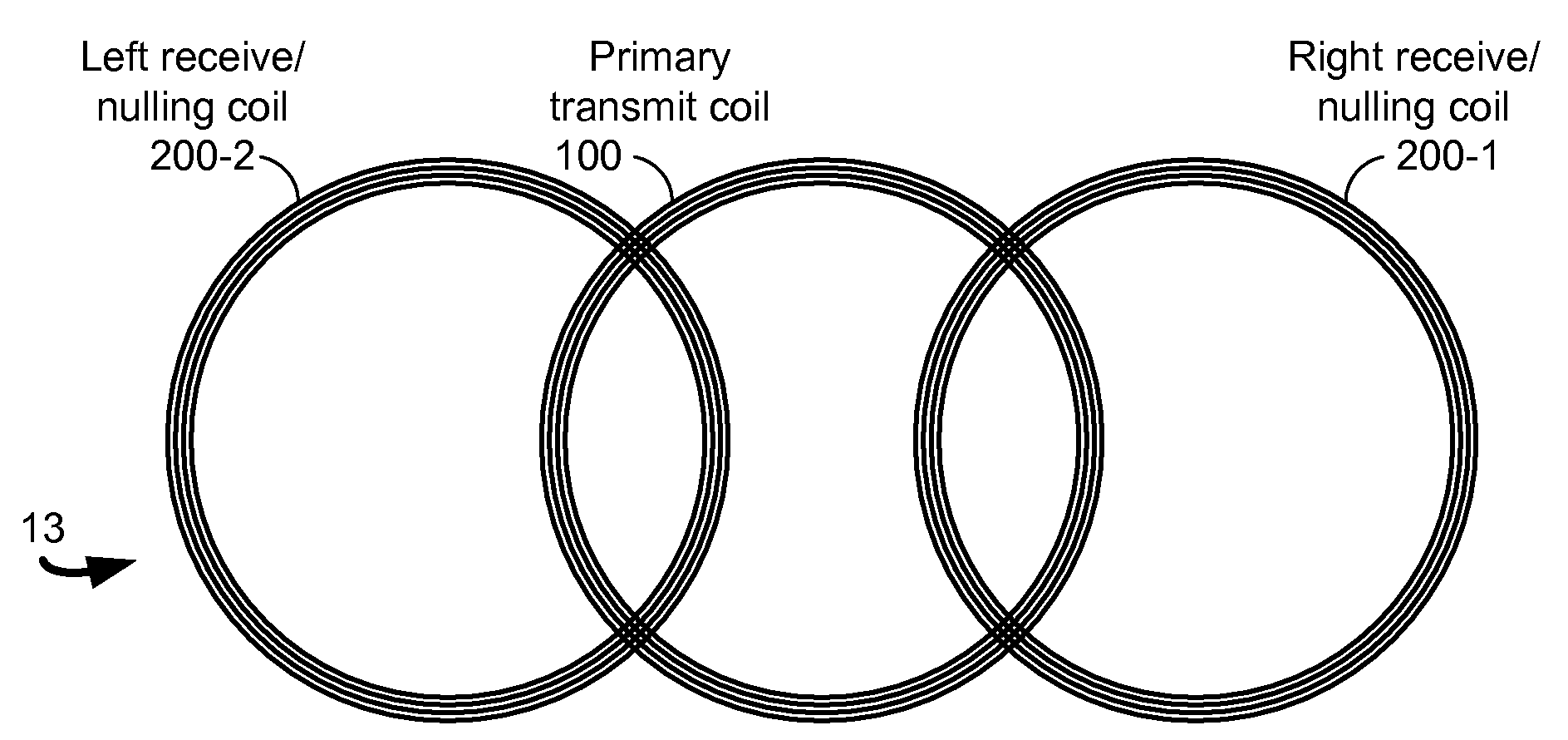
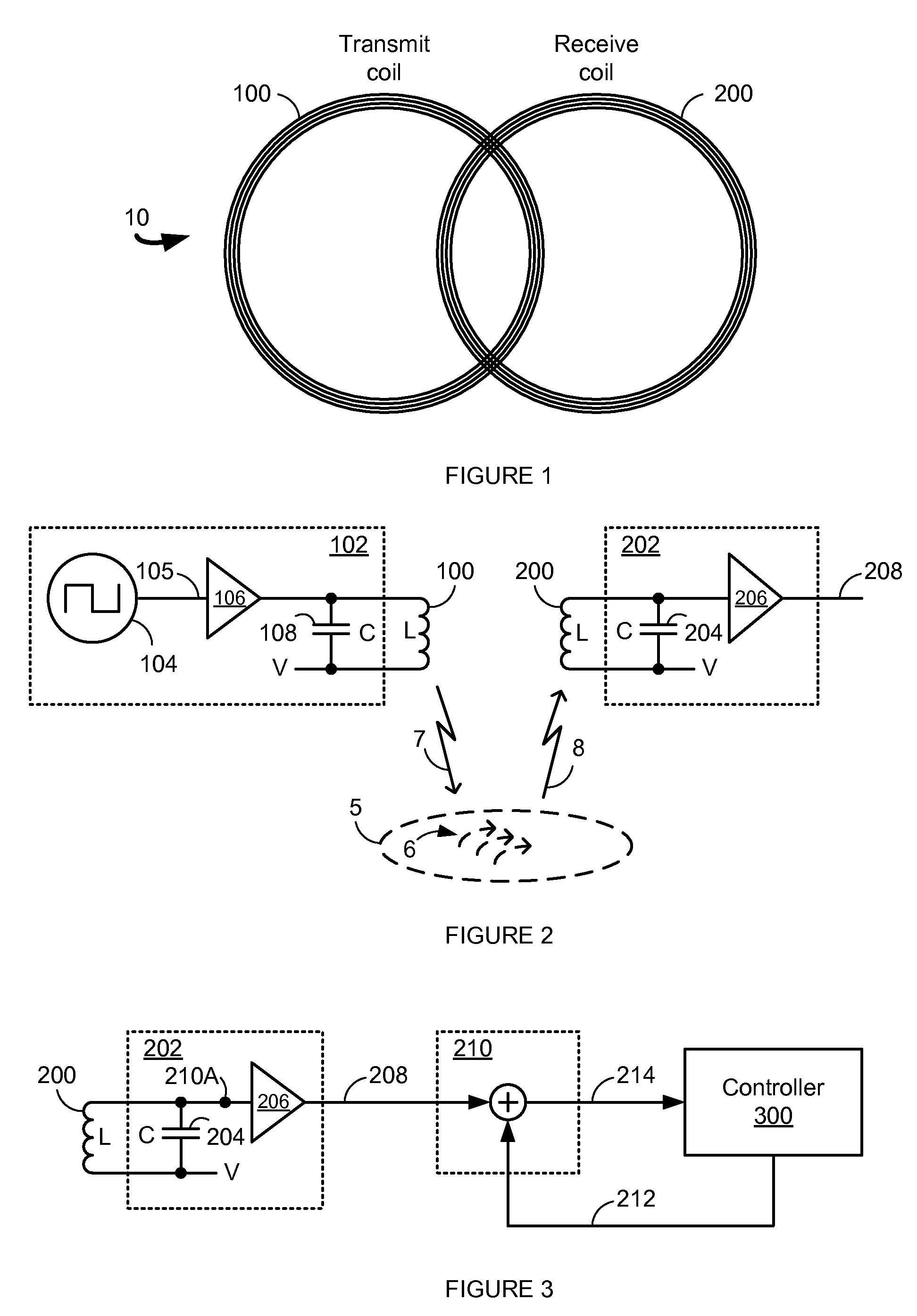
[0026]FIG. 1 illustrates a coil Configuration 10 of a metal detector having two coils: transmit coil 100 and receive coil 200. In Configuration 10, the coils are coplanar but are not coaxial and are formed, sized and positioned such that the receive coil 200 produces substantially no output signal in the absence of a metallic object. That is, the relative physical positioning of the transmit coil 100 and the receive coil 200 provides positional nulling.

[0027]In operation, the metal detector applies an alternating current to the transmit coil 100, which...


PUM


Abstract

An implementation of a direction finding and magnetic nulling metal detector is provided. Some embodiments of the present invention provide for a metal detector having multiple resonant circuits and associated coils for transmitting a primary transmit signal, transmitting a magnetic nulling signal, and receiving a receive signal. A controller includes logic to process the generate the transmit signals and to process the received signal in order to determine a gradient vector along one or two dimensions, a depth and whether or not a metal object is ferrous.

Description

BACKGROUND OF THE INVENTION[0001]1. Field of the Invention[0002]The invention relates to tools and in particular to a metal detector, for finding a metallic object hidden behind a surface and for providing a directional indication.[0003]2. Background of the Invention[0004]Metal detectors are well known tools used to find ferrous and non-ferrous materials sometimes hidden behind or under a surface. For example, see U.S. Pat. No. 3,471,722, U.S. Pat. No. 3,823,365, U.S. Pat. No. 3,826,973, U.S. Pat. No. 3,882,374, U.S. Pat. No. 4,030,026, U.S. Pat. No. 4,110,679, U.S. Pat. No. 4,659,989, U.S. Pat. No. 4,667,384, U.S. Pat. No. 4,700,139, U.S. Pat. No. 4,709,213, U.S. Pat. No. 4,783,630, U.S. Pat. No. 4,868,910, and U.S. Pat. No. 5,729,143, each of which is incorporated by reference.[0005]Such detectors often use an inductive coil for finding metal. The coil may be wound such that it occupies a 2-dimensional plane or near plane or alternatively may be wound laterally around a center cyl...

Claims


Application Information

Patent Timeline
IPC IPC(8): G01V3/11G01V3/165
CPCG01V3/107
Inventor HEGER, CHARLES E.ROSSETTI, ANTHONY J.
Owner ZIRCON
Why Eureka
Try Eureka