Metal detector

a metal detector and metal detector technology, applied in the field of metal detectors and metal detectors, can solve the problems of complex establishing an adjustable balance signal to nullify or reduce unable to achieve the effect of nullifying the output signal, and unable to achieve the effect of reducing the so as to achieve the effect of compensating for any imbalance in the output signal, reducing the complexity of the establishing balance signal, and reducing the frequency rang

Active Publication Date: 2015-08-20
ILLINOIS TOOL WORKS INC
View PDF4 Cites 26 Cited by
  • Summary
  • Abstract
  • Description
  • Claims
  • Application Information

AI Technical Summary

Benefits of technology

[0030]Preferably, the adjustable balance signal is based on the drive signal having a phase and amplitude component that is adjusted so that it is substantially equal and opposite to the output signal. Preferably, at a given operational frequency of the metal detector, the adjustable balance signal is varied by increasing or decreasing the adjustable balance signal in sequential steps. At each step, the output signal is measured to see if it has reached below a predetermined threshold value. If not, the adjustable balance is incremented and the measuring process repeats to see if it has reached below a predetermined threshold value. Once the output signal reaches below a predetermined threshold value, the adjustments made to the adjustable balance signal at a given frequency are stored in a database or look-up table for later retrieval at that given frequency. By varying the adjustable balance signal through a trial and error process help to mitigate the complications in mathematically establishing a cancelling signal for any imbalance in the output signal.
[0031]Preferably, the process of calibrating the metal detector by nullifying the output signal or balancing the coil system is repeated for successive frequencies. Preferably, the frequency is varied incrementally, more preferably in substantially 10 Hz increments. This is made possible since the process of balancing the coil system is automated. More preferably, the adjustable balance signal can be varied by software. Whereas in prior art metal detectors only a select few frequencies are subjected to the balancing process due to the time and effort to physically adjust the separation of the coils to compensate for the level of imbalance, controlling and varying the adjustable balance signal through the use of software to quantitatively measure the level of imbalance of the coil system and automatically configure the drive signal to bring it into balance automates the balancing process and thereby a greater range of operational frequencies can be subjected to the balancing process.
[0032]Preferably, the adjustable balance signal is varied by a potentiometer, more preferably a digital potentiometer. The use of a digital potentiometer enables the adjustable balance signal to be controlled by software. This allows the system to automatically nullify any imbalance in the system, i.e. compensate the output of the coil system by the adjustable balance signal to provide a compensated signal. The use of one or more potentiometers allows the balancing signal to effectively compensate for any imbalance in the output signal irrespective of the shape or form of the output signal. This is even possible where the coil system is driven by a plurality of switches as taught in WO 2006 / 087510 (Spectrum Inspection Systems Limited), where the resulting square wave (or a trapezoidal wave) generates a large number of relatively high energy harmonics compared with the conventional sinusoidal signal generated by a tuned circuit. Preferably, the potentiometer comprises a first potentiometer and a second potentiometer and the adjustable balance comprises a first adjustable balance signal and a second adjustable balance signal. The first adjustable balance signal is varied by the first potentiometer and the second adjustable balance is varied by the second potentiometer. Preferably, the first adjustable balance signal is substantially not in phase with the second adjustable balance signal. More preferably, the first adjustable balance signal is out of phase with the second adjustable balance signal by equal to or less than substantially 90°. It has been found that the further apart the first and second adjustable balance signals from 90°, the more difficult it would be for the adjustable balance signals to balance any imbalance in the output signal. Preferably, the first adjustable balance signal is in phase with the drive signal and the second adjustable balance signal is not in phase with the drive signal. Preferably, the second adjustable balance signal is out of phase with the drive signal by substantially 90°. Equally, the first adjustable balance signal and / or the second adjustable balance can be set at any arbitrary angle that is not in phase with the drive signal or not in phase quadrature (90° out of phase with the drive signal) with the drive signal respectively. Varying the balance signal by two potentiometers allows the full 360° phase angle of the output signal to be covered. Optionally, the adjustable balance signal can be varied by a tuning circuit comprising a variable resistor (potentiometer), a variable capacitor and / or a variable inductor. In contrast to two potentiometers, a tuning circuit comprising a potentiometer, a variable capacitor and / or inductor only allows 90° phase angle variation of the drive signal to be covered.
[0033]More preferably, the adjustable balance signal is varied by an Electronic Programmable Logic Device (EPLD), e.g. a Complex Programmable logic device (CPLD) or Field Programmable Gate Array (FPGA). Coupled to an EPLD, a CPU selects a drive map stored in the EPLD or in the CPU which then sends signals to a driver to generate both drive signal and adjustable balance signal at a given working frequency. For example, the driver comprises a plurality of switches, e.g. FETs, such that through a selection of the drive map stored in the EPLD, the EPLD controls an internal clock oscillator to drive a plurality of switches, e.g. FETs, to create the transmitter drive signal at a given frequency. As the adjustable balance signal is derived from the drive signal, the adjustable balance signal will be at the same frequency as the drive signal. In addition for generating the drive signal and the adjustable balance at a given working frequency, the CPU coupled to the EPLD can also be used to vary the amplitude and phase of the generated adjustable balance signal. This removes the need for a potentiometer or tuning circuit as the variation in the adjustable balance signal can be done purely through use of programmable logic circuits (PLCs).
[0034]The adjustable balance signal in step (a) and / or the combined adjustable balance signal and / or the output signal in step (b) above is filtered by a low pass filter, more preferably a switchable low pass filter to cater for the different operating frequencies. Whereas in known auto-balance systems, the system is based on a regular sinusoidal wave generated over a limited range of frequencies by means of a tuning circuit, the output from a variable frequency metal detector whereby the drive coil is driven by a plurality of switches, generates a square wave (or trapezoidal wave) with a large number of high energy harmonics or harmonic distortions along with the fundamental frequency of operation, i.e. the resultant wave typically has an uncontrolled shape. In absence of the low pass filter, the detector runs the risk that the peak signal voltage of the compensated signal as a result of the harmonics may exceed the predetermined threshold value of the compensated signal resulting in a continuous imbalance. More importantly, the peak signal voltage may exceed the saturation limit of the detection circuitry. The low pass filter filters out one or more harmonics from the adjustable balance signal and / or the output signal leaving the fundamental component, i.e. generates a more sinusoidal waveform that is more workable and measurable and is not disrupted by the high energy harmonics.
[0035]The adjustable balance signal and / or the output signal can each individually be filtered by one or more low pass filters to remove one or more harmonics from their respective signals prior to being combined to form the compensated signal. The low pass filter also allows the adjustable balance signal to be effectively varied by the potentiometer or PLC or otherwise so as to compensate for any imbalance in the output signal irrespective of their shape or waveform or the presence of any harmonic distortion. This simplifies the ‘balancing’ operation, because less steps are needed to reach a balanced state since the signal has a waveform that is more “manageable” (generates a more sinusoidal waveform) than a signal with a waveform having no regular shape.

Problems solved by technology

This is effectively nullifying the output signal.
Thus, establishing an adjustable balance signal to nullify or reduce the imbalance in the output signal is more complicated than where the output signal is sinusoidal in nature.
Simply establishing an equal and opposite signal to cancel the output signal is not always appropriate in this case.
The algorithms to achieve this can be more complicated than simply adding or subtracting the signals, as one would expect from a signal from a traditional tuning circuit.

Method used


Image

  • Metal detector
  • Metal detector
  • Metal detector

Examples


first embodiment

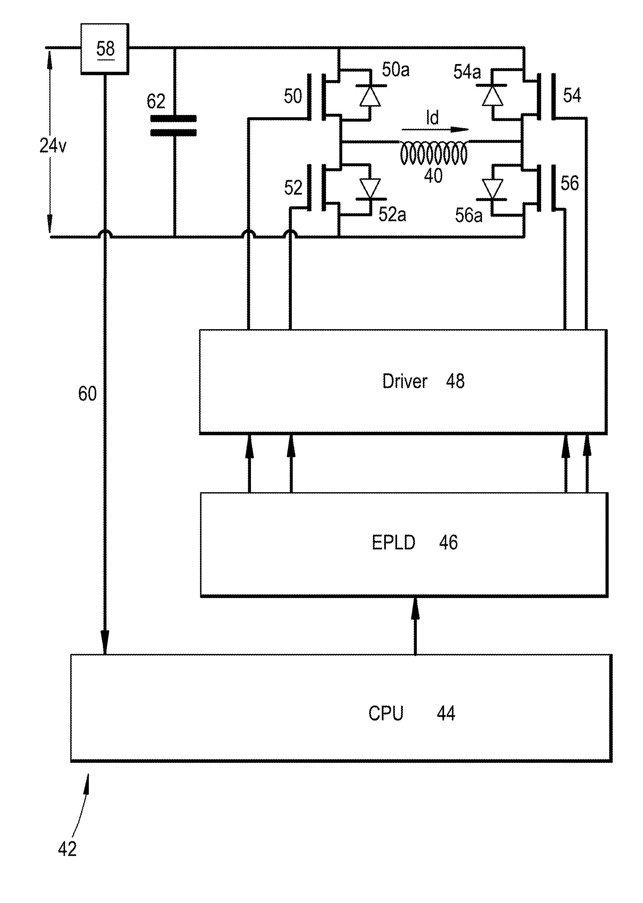
[0094]FIG. 8 shows a circuit diagram 70 of the present invention, which is an adaption of the circuit diagram described in the international patent application WO 2006 / 087510, and thus the components in common behave similarly. In summary, the driver circuit shown in FIG. 7 is represented by the dashed outline / box 42. The driver circuit 42 comprises a central processing unit (CPU) 44, an electrically programmable logic device (ELPD) 46 and a driver 48 connected to four field effect transistors (not shown) for simplicity. For simplicity, the driver 48, FETs (50 to 56) and the diodes (50a to 56a) of FIG. 7 are represented as the “driver”48. The EPLD 46 stores a plurality of drive maps, each drive map containing a switching sequence for the switches (FETs) to drive the drive coil 40 at a respective predetermined operation of frequency of the metal detector. The CPU 44 selects an appropriate drive map from a plurality of drive maps stored in the electronically programmable logic device ...

third embodiment

[0126]The flowchart in FIG. 14 shows an example of the sequence of steps used to calibrate any imbalance in the metal detector for a particular product type under investigation with reference to the potentiometers as shown in FIG. 8a. However, the sequence of steps shown in the flowchart in FIG. 14 is applicable to the other embodiments where the adjustable balance signal is varied by a tuning circuit or the EPLD. The first stage of the process involves the selection of the ideal frequency of operation of the metal detector for a particular product 136 under investigation. This is usually done manually depending upon the operator's experience but can be done automatically as described above. Once the frequency is selected, the processor then sets the metal detector to operate at that frequency. The system then searches the database and retrieves the stored adjustment of the potentiometer 138 from the earlier calibration process (see FIG. 11a) at the corresponding operating frequency...


PUM

PropertyMeasurementUnit
frequencyaaaaaaaaaa
frequenciesaaaaaaaaaa
thresholdaaaaaaaaaa

Abstract

A method of operation of a metal detector having a driver circuit for establishing an alternating magnetic field in a coil system so as to generate an output signal at a given frequency, the method comprising the steps of
    • a. generating an adjustable balance signal;
    • b. combining the adjustable balance signal with the output signal of the detector.
    • c. varying the adjustable balance signal so as to provide a compensated signal.

Description

FIELD OF INVENTION[0001]The present invention relates to an apparatus for detecting contaminants. More particularly but not exclusively the present invention relates to an apparatus for detecting metal in foodstuffs.INTRODUCTION[0002]Foreign bodies in their products are one of the biggest sources of customer complaints for many food manufacturers and retailers. Such foreign bodies can be any undesirable solid objects and include items entirely unconnected with the food such as glass or metal fragments, as well as those related to the food such as bones. One of the biggest concerns for the food processing industry is the unwanted inclusion of metallic particles or metallic items in the food product as a result of processing. For example, typical metal inclusions range from nuts or washers lost from the processing machinery or dropped during maintenance etc, to metal shavings, e.g. produced by mechanical wear.[0003]Such metal inclusions will not only compromise product safety and rais...

Claims


Application Information

Patent Timeline
Patent Type & Authority Applications(United States)
IPC IPC(8): G01V3/10G01N27/90
CPCG01N27/9033G01V3/10G01V3/107G01N33/02G01V3/101G01V13/00G01V3/105G01V3/104G01N27/9006
Inventor MOORE, JOHN COLINTAGG, COLIN MICHAEL
Owner ILLINOIS TOOL WORKS INC
Why Eureka
Try Eureka