System and method for measuring conductivity of fluid

a technology of conductivity and resistivity, applied in the direction of fluid resistance measurement, liquid/fluent solid measurement, instruments, etc., can solve the problems of ion migration in the fluid, dc signal, polarization, and the conductance cell often encountering additional electrical processes

Active Publication Date: 2008-12-04
GEORG FISCHER SIGNET
View PDF20 Cites 18 Cited by
  • Summary
  • Abstract
  • Description
  • Claims
  • Application Information

AI Technical Summary

Benefits of technology

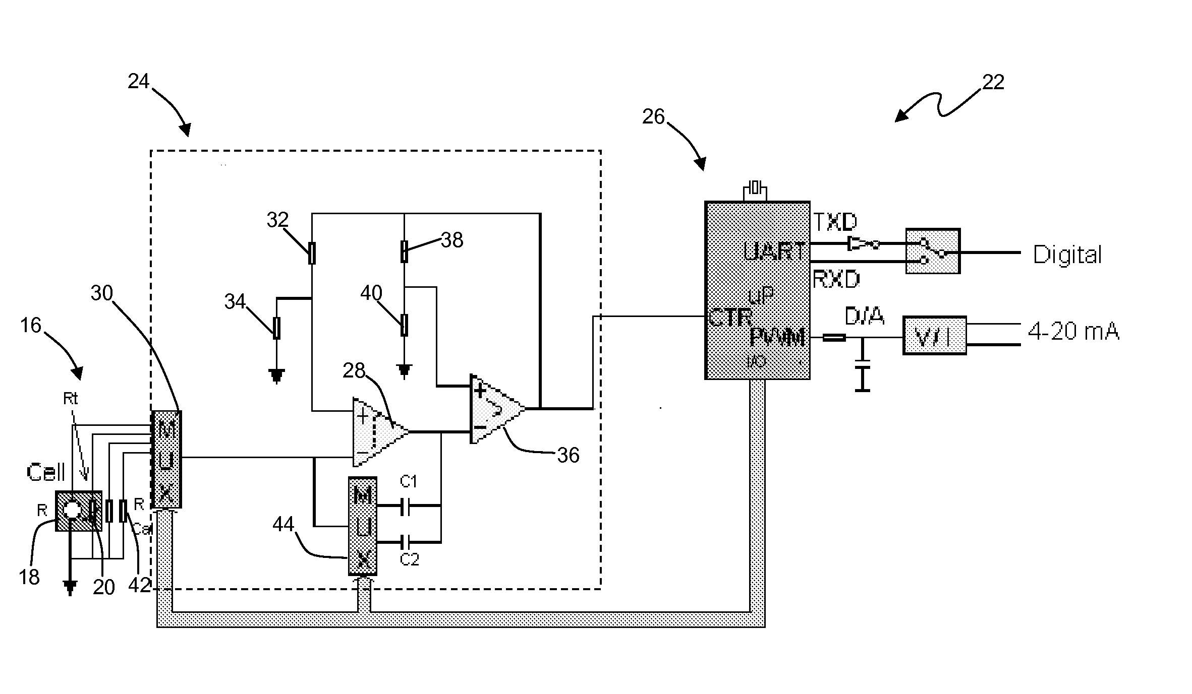
[0018]In general terms, the present invention provides system for measuring conductivity of a fluid. The system is configured to calibrate for wire capacitance, during use, to minimize error in conductivity measurement of the target fluid. The system includes a signal generator configured to drive a conductivity cell and a temperature element, with an alternative current (AC) drive signal, to include (a) driving the temperature element with a first drive signal having an initial frequency that is greater than or equal to zero, resulting in a temperature measurement, (b) driving the temperature element with an second drive signal having an initial frequency that is greater than the initial frequency of the first drive signal, resulting in a compensation measurement, and (c) driving the conductivity cell with an AC drive signal having a third frequency greater than the first frequency, resulting in a raw conductivity measurement. The term “raw conductivity measurement,” unless otherwise specified, is intended to refer to and be inclusive of a conductivity value prior to compensation for wire capacitance effects.
[0019]The system further includes a processor assembly electrically coupled to the conductivity cell and the temperature element to calculate a conductivity value of the fluid. The conductivity value is a function of the values of the temperature measurement, the compensation measurement, and the raw conductivity measurement, thereby compensating the conductivity value for capacitance effects. In this manner, the system effectively compensates for capacitance attributable to wiring extending between the electrode and other electronics of the system, usable with wiring of varied and unknown lengths.

Problems solved by technology

In practice, however, such conductance cells often encounter additional electrical processes that must be considered.
DC signals are problematic in that they tend to cause ion migration in the fluid and polarization, among other things.
Such errors are exceeding difficult to characterize with any accuracy, making DC signals impractical for such conductivity sensors.
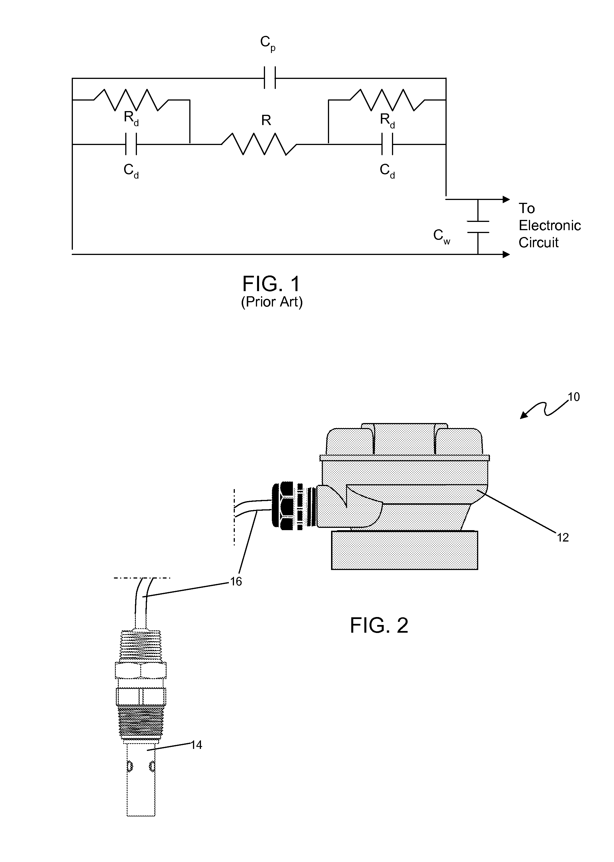
However, capacitive effects of wiring used to connect the electrodes to other electronics of the system is commonly referred to as wire capacitance (Cw), and tends to contribute to measurement error.
Wire capacitance tends to be difficult to characterize, particularly without detailed knowledge of parameters of the wire.
Moreover, minimizing the length of the wire or cable reduces the capacitance effect.
Although the aforementioned approaches are generally effective, shortfalls existed.
A user cannot modify the length of the cable used, even if desired.
Thus, a customer cannot use an electrode from other vendor, which may use different material, wire gauge and length; since high measurement errors may occur.
Some attempt to minimize capacitance effects by using complex circuitry and processes, which raises different issues.
Such approaches, however, require drive signals at comparatively low frequencies, which increase the risk of polarization, and require wiring or cables that are relatively short, and the user is limited in the length of cable that can be used.

Method used


Image

  • System and method for measuring conductivity of fluid
  • System and method for measuring conductivity of fluid
  • System and method for measuring conductivity of fluid

Examples


example

[0055]In an exemplary test, the system assembly includes a sensor having stainless steel electrodes with a cell constant of about 1.0, coupled to an electronics subsystem. To provide a baseline, the sensor assembly was operated without benefit of capacitance compensation sequence. Thereafter, the sensor assembly was operated with benefit of the compensation sequence. During both testing sequences, the length of the cable connecting the sensor to the electronics was varied from 3 inches to 15 feet, with measurements taken used both lengths of cables. In this manner, the benefit of the capacitance compensation can be demonstrated

[0056]In the baseline test, the sensor was driven by high frequency signal and measurements of conductivity and temperature were taken of a standard conductivity solution of 1000 uS / cm±0.25% at 25° C. The cable having a length of about 3 inches was used. The system resulted in an error of +0.65% for conductivity and an error of +0.3° C. for temperature. Next, ...


PUM


Abstract

A system and related method are provided to calibrate for wire capacitance during use to minimize error in conductivity measurement of the target fluid. The system includes a signal generator configured to drive the conductivity cell and the temperature element, with an alternative current (AC) drive signal having variable parameter. The system further includes a processor assembly electrically coupled to the conductivity cell and the temperature element to calculate a conductivity value of the fluid. The conductivity value is a function of the values of the temperature measurement, the compensation measurement, and the raw conductivity measurement, thereby compensating the conductivity value for capacitance effects. In this manner, the system effectively compensates for capacitance attributable to wiring extending between the electrode and other electronics of the sensor, usable with wiring of varied and unknown lengths.

Description

BACKGROUND OF THE INVENTION[0001]The present invention relates generally to a system for measuring conductivity or resistivity of a fluid and, more particularly, to such systems that further measure temperature and compensate for capacitance effects.[0002]Conductivity / resistivity sensors have long been used to measure ionic concentration in target fluids. Measurement of conductivity or resistivity of a fluid provides useful information in varied industrial applications. Such measurements aid determining purity of fluid and detecting contamination or chemical concentration of fluid, in industrial processes across many industries such as pharmaceutical, food, chemical, wastewater treatment, and semiconductor manufacturing. Temperature sensing of the target fluid also provides useful information in industrial processes and can be used to compensate conductivity measurements based on the temperature of the fluid, since the conductivity of a given fluid is a function of temperature.[0003...

Claims


Application Information

Patent Timeline
Patent Type & Authority Applications(United States)
IPC IPC(8): G01R27/26
CPCG01R27/22
Inventor ZHOU, QINMINGBURKHARDT, GERT
Owner GEORG FISCHER SIGNET
Why Eureka
Try Eureka